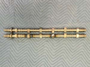
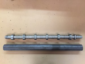
Cam cores done!

IMG_0573


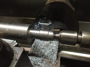
Had a problem with my 3D model for the lobes. I didn’t catch it until it messed up 2 lobes. It was right on the edge of not needing a weld but I figured better safe than sorry.

They are boxed up and heading to Isky today. 6 days to get there, 6 to 8 weeks to grind, 6 days back. Now I know how my customers feel:)

I’ve got plenty to do. The manifolds are on the way to me so I can get that all squared away. Then the valve cover.

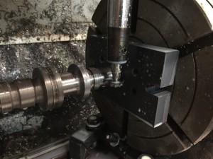
Machining the cam lobes

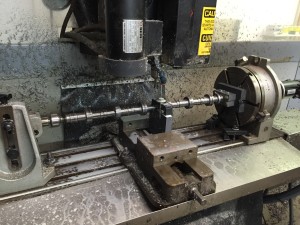
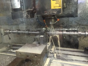
Got the 4th axis back up in the mill and decided it was time to do the lobes. My plan is to rough it out on one plane then rotate 90 degrees and rough again. Repeat at 180 and 270 degrees. I’m hoping there is enough material removed at that point to go straight to the grinder.

First step key slot.

IMG_0563

After this is done I have a fixture that clamps on the front and keeps the cam indexed to the 4th axis.

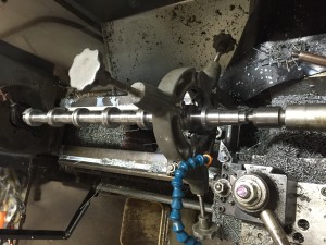
I machined a V block in line with the centerline of the cam and added a clamp. This is way too long to machine without a center support.

IMG_0564

First cut!

IMG_0565


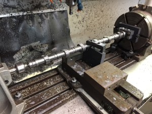
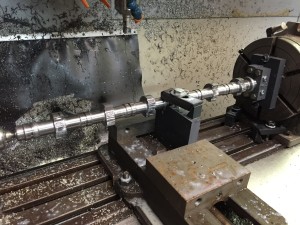
This is after the first roughing pass. I’m using  .035 depth of cut which is leaving a bit of a step. I may make it a little less on the next cut. If I decide to do a finish pass that will all go away.

IMG_0566

Here I’ve rotated it 90 degrees. I also rotate it in my CAM program so it’s looking at it from the new direction when I calculate the new code.  4th axis work can be tricky if everything isn’t setup properly.

IMG_0568

Well that’s it until Monday.

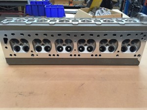
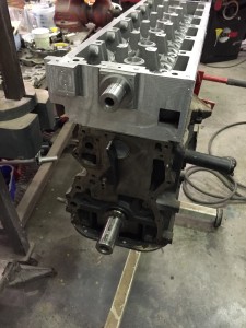
Got The Head Back From Mazworx

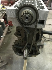
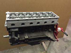
Starting to look like a finished product.

IMG_0547


I was really happy to find out when I dropped the head off to find out that Jim Thompson formerly of Sunbelt Engines is now doing head work at Mazworx. He did all the work on the head. I wasn’t in a position to post about it then as I didn’t get his permission to mention it. It really felt good knowing “an old hand” was going to be doing the work.

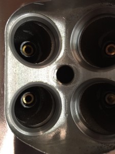
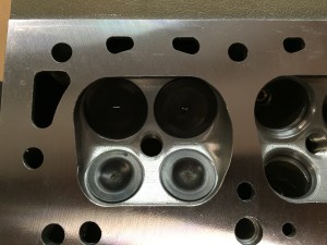
I knew there was going to be a little bit of an issue with the exhaust seats as I had to move the valves from their original position. There is a step on one side that I can blend and a ledge on the other side. None of us feel it’s going to be a problem for this build. The next design will have a smaller as cast seat area so there will be more meat.

IMG_0550

The other issue is for some reason I felt it was a good idea to put a boss inside the port for the valve guides. They won’t be in the next gen either. There is plenty of meat for the guides without the bosses.

I’ve waited a long time to see this:

IMG_0549

Let’s Talk Camshafts

Camshaft development took place at multiple times over multiple months so I decided to condense it into one post.

I started out thinking I would call any of the Honda K20 cam mfg that offered “custom cams” on their web page and have a 6 cylinder version of one of their cams made. Well custom means custom grind. If you don’t have the core then they cant do the grind. So I went in search of having custom cam cores produced. There aren’t too many core manufacturers out there and even fewer that will talk to a privateer like me. The best price I got was like $2800.00 for 2 cams if I bought them in quantities of 8. And this was just for the core. It would still have to be final ground.

I then proceeded to educate myself about cores. I indirectly work with a steel foundry that pours 8625 steel. I decided to give that a try. I made a set of patterns and had 2 sets of cams cast. I wasn’t happy with the results. I discussed the issues with the foundry and ordered another set. While I was waiting I started to listen to all the people on HybridZ that recommended I machine my own cores out of 8620 round stock. I bit the bullet and ordered a 20 foot length of 2″ round.

Before and after. From 22 lbs down to 7 lbs

IMG_0543


Started out by turning down the entire OD and then The back end

IMG_0533

Then I flipped it around and started a carvin!

IMG_0537


Next up will be cutting the lobes in my mill


Header Flange

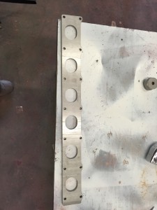
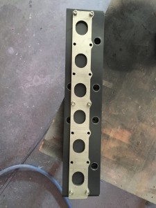
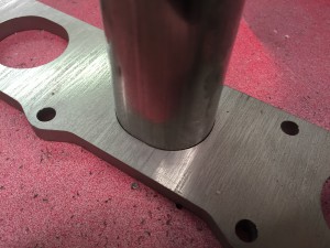
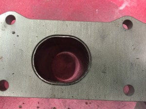
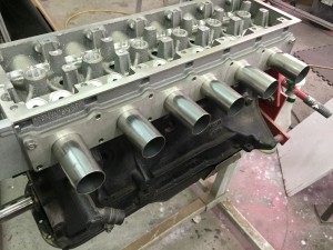
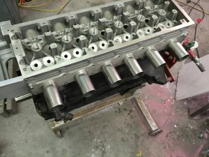
Xnke from HybridZ is making the header for me. I had the flange laser cut from stainless 304.

IMG_0337

I made an adapter block that bolts on a stock head and positions the flange where it will be with the KN20 head.

IMG_0348

Made a mandrel to form the stubs into an oval.

IMG_0382

Really happy with the fit

Remember kids good fabrication is all about joinery. The better the fit the smaller the weld. The smaller the weld the less the warp.

IMG_0383


This is nice to see.

IMG_0385

IMG_0384

Front Timing Cover

Today I was able to finish up the machine work on the timing cover and head.

The timing cover is a bit of a kludge as I had printed the mold before I fully finalized the timing cover. It works but it will be better in future versions. I had to get it cast and on the head so the machine shop could surface it all together.

Here I’ve mounted the cover to the front of the head, machined the surface flush with the bottom and drilled the front holes for the lower cover.
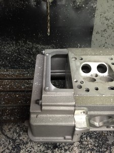
IMG_0350

The front lip is a little thin. I’ll add material to the pattern to thicken it up. I really should have left more material around the entire head. That way I could have made a cleanup pass around the whole thing. I have enough material on the valve cover to create a lip to hide it so it will look good when it’s buttoned up. This head will have a water outlet on the side of the timing cover but future heads will use a coolant manifold like the OSG head.
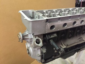
IMG_0353

Very happy with the internal fit. I need to rig something for the front cover bolts. The holes are right on the step. I’ll add bosses to the pattern so it won’t be a problem later on.
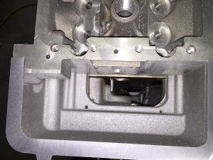
IMG_0352

So I didn’t try to make it fit this well but the “as cast” fit between the factory cover and my cover couldn’t have been better. Of course it’s in a spot where no one will see it :)

IMG_0355


IMG_0351


Front Section Machining

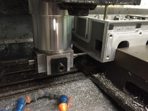
Machined the front of the head. I knew this was going to be a PIA from the word go. I just don’t have a proper angle milling head to really go at it.

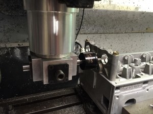
I bought a used angle head on ebay a few years ago. It’s designed for woodworking but it was cheap so I went for it. In the first shot I’m using the probe to indicate off of the cam bores.

IMG_0310

Here I’m surfacing the front of the head. The finish came out a lot better that I expected considering the rigging I had to do to make it work.

IMG_0311

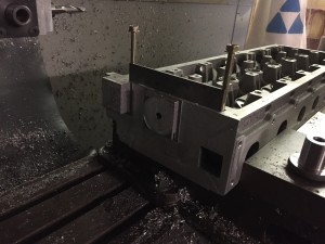
Faced the upper timing chain tensioner and the upper chain idler mount, spot drilled the timing cover and tensioner holes. I’m going to drill and tap those manually as I didn’t have anyway to hold drills in that angle head. No biggie.

IMG_0312

Got lucky on the pilot bore on the idler mount. You have to tap it on with a plastic hammer.

IMG_0315

The chain fits well. I knew I was going to make a spacer set for the bottom gear since it’s a single not a double like the stock chain. The single chain tracks along the center of the guides now which is what I was looking for.

IMG_0316

X-ray results

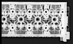
Got the head back from X-ray on Saturday. No big surprises.

Here is a shot of the front half

rad2_zpshzqv1wte

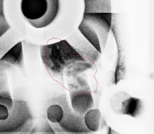
Here is a closeup of a known shrink porosity problem.

rad1_zpsrvmsuoes

I knew it was there because you can see it from the top. I wanted to leave it to see what it looked like in the X-ray. You can see it leads all the way over to the valve guide bore and in fact you can see it in the bore. I’ll do a weld repair on the top and call it a day as it’s too small a defect to affect the valve guide.
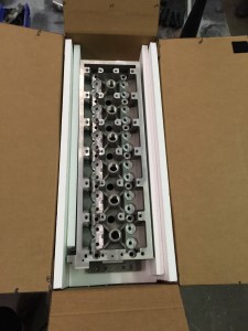
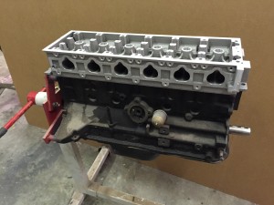
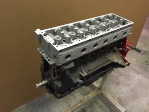
Controlling solidification shrinkage is one of the tougher aspects of casting metal. We’ll try something a little different on the next one.

Every head will be x-rayed before they get sold. This way people can have confidence in the casting before they invest in machining.