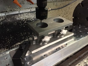
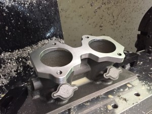
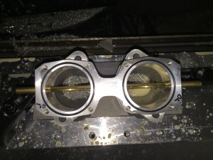
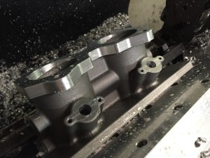
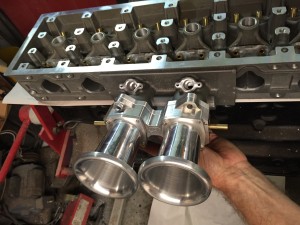
Got started on the first manifold.
Probing the ports. This will establish my zero point. The cores were 3D printed and the ports ended up being 90.114mm apart. I can handle .114mm:)
Action shot of the fly cutter doing the finish pass. on the flange.
In order to make the linkage that came with my ITB kit work I needed to shift the ports .025” It is going to be a lot easier to blend the shift than rework the linkage.
I didn’t have a CAD drawing of the ITB so I traced around it, scanned it and then imported it into my CAD program. I’m happy with the fit.
WFO
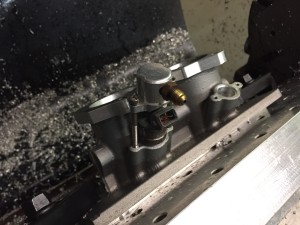
Working on the injector bungs. I drilled all the way through with a .4375” bit then opened it up to .655” part way down. I use the method described here:
http://www.sdsefi.com/techinta.htm
It leaves an air gap around the injector body and help guard against heat soak. It’s the same method I used on my manifold and it survives August heat in Florida.
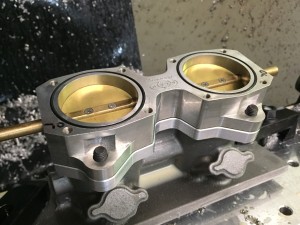
I pulled one of the injectors out of may car for a test fit.
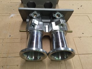
That’s going to look really good!
Now that’s my kind of selfie:)
