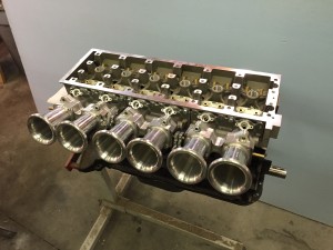
Had the head flow tested

So I took the head down to Scott’s Racing engines to get it Flow tested.

IMG_0662

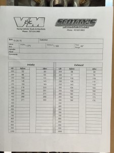
The before column is a raw port with only the machine work for the port matching done. The after has been cleaned up really quickly with a double cut round burr and then I hit it with a cartridge roll on a mandrel. All I did was remove the sand casting texture, blend the steps between the seats and ports, and remove the additional material from the halve guide bosses.

IMG_0666


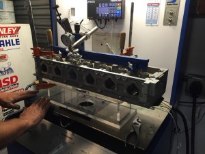
The clear acrylic manifold Had a 3.5″ bore.

They applied modeling clay to the intake ports to smooth the air entry and they held a tube against the exhaust port to simulate a header.

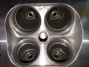
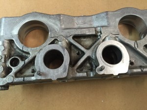
Here is the before port. You can see the steps between the valve seats and the ports are still there and the valve stem bosses are too long.

IMG_0672

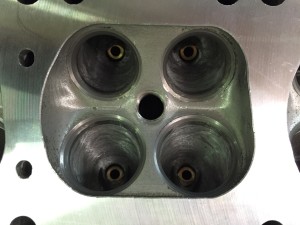
Here is my piss poor after port. You can see there is plenty of room for improvement with my porting abilities:)

IMG_0674

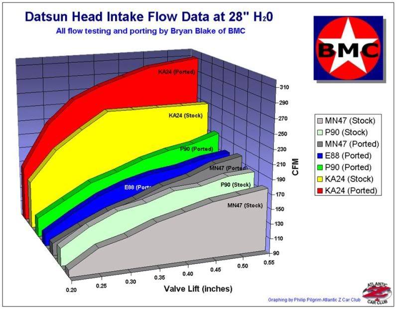
This is a flow comparison chart don by Bryan Blake of BMC. If I trust anyones numbers it would be his. As you can see my head is well above the stock KA and really close to Bryan’s ported KA.

post-1083-0-89085500-1446163474


They are just initial numbers but they do follow what I hoped to see based on my port volumes. When I was designing it I looked up the kind of volumes the K20 head gurus were running and I tried to hit those marks. Especially on the intake. The exhaust is fairly close to the stock K20 in shape but the intake is mine from scratch. I started with the stock entry and exits and made it look pretty in between.
Oil distribution

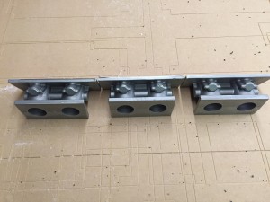
Started working on cam tower mods and oil distribution. The plan is to pull oil from the oil pressure switch bung and Tee it to the front and the back. The front was pretty easy because I had incorporated material in the casting. The rear…Meh not somuch.

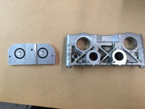
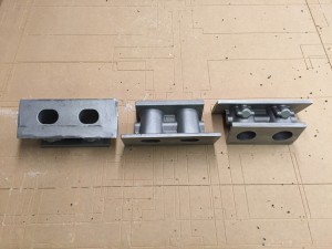
Production heads will most likely use the #1 cam tower at the back to supply oil but that was proving to be impractical on the prototype so I opted for a different path. I took an extra #2 tower and made a manifold plate to bring the oil in.

IMG_0657

I doweled both pieces to maintain alignment. I tapped the tower and it’s held together with three screws sandwich style.

IMG_0658

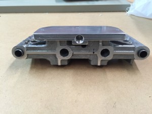
Oil is fed in the bottom. and it’s cross drilled and plugged to supply the shafts

IMG_0659

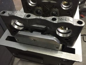
Tight fit but it will work.

IMG_0660


And then there were three…..

IMG_0652

IMG_0649


Here are some process shots for those of you that are interested.

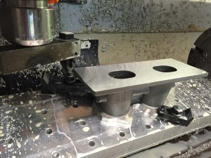
After rough surface and fly cutting.

IMG_0635

Outlining the flange.

IMG_0636

IMG_0637

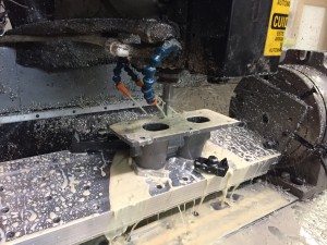
O-ring groove.

IMG_0640

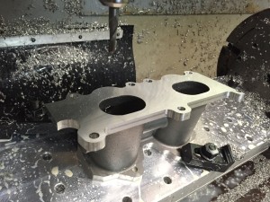
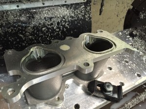
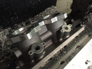
Port matched and injector clearance machined in. I’ll hand finish the injector area.

IMG_0641

Made some progress on the manifolds

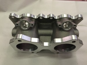
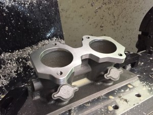
Got the manifold to head flange done. I still need to de-burr the sharp edges but I’m happy with the results.

IMG_0638

IMG_0639

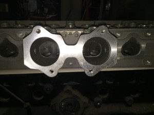
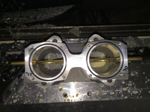
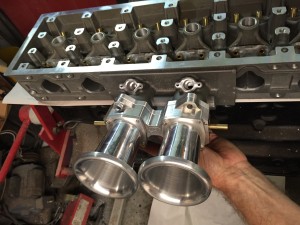
Hard to tell in this picture but the ports match really well.

IMG_0630

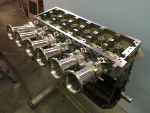
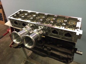
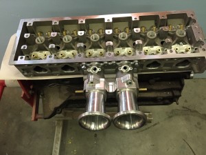
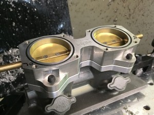
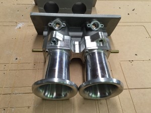
1/3 of a money shot:)

IMG_0631

IMG_0634

Should be able to finish up the other 2 tomorrow. Now If I could just get my valve cover I’d be set for a while.


Today….Was a good day…

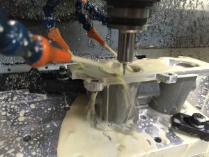
Got started on the first manifold.

Probing the ports. This will establish my zero point. The cores were 3D printed and the ports ended up being 90.114mm apart. I can handle .114mm:)

IMG_0615

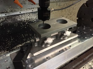
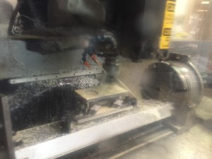
Action shot of the fly cutter doing the finish pass. on the flange.

IMG_0616

In order to make the linkage that came with my ITB kit work I needed to shift the ports .025” It is going to be a lot easier to blend the shift than rework the linkage.

IMG_0617

I didn’t have a CAD drawing of the ITB so I traced around it, scanned it and then imported it into my CAD program. I’m happy with the fit.

IMG_0618

WFO

IMG_0619

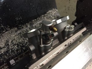
Working on the injector bungs. I drilled all the way through with a .4375” bit then opened it up to .655” part way down. I use the method described here:

http://www.sdsefi.com/techinta.htm

It leaves an air gap around the injector body and help guard against heat soak. It’s the same method I used on my manifold and it survives August heat in Florida.

IMG_0620

I pulled one of the injectors out of may car for a test fit.

IMG_0621

That’s going to look really good!

IMG_0624

Now that’s my kind of selfie:)

IMG_0623


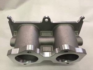
Got the manifolds!

Finally got my intake castings in. They came out pretty good. I may need to tweak my pattern a bit.

IMG_0609

A good part of the flanges will be machined away. I purposely made the a lot larger than I needed. I like options.


I left the intake to head port as an oval. I will machine in the injector port area after I have drilled the injector bung.

IMG_0610

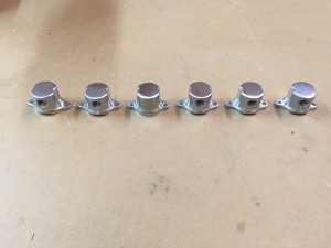
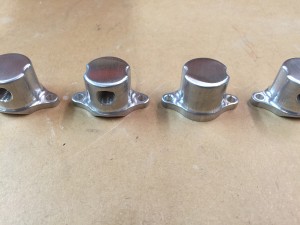
While I was waiting for the castings I went ahead and made my injector caps for the hard lines.


IMG_0582

Not perfect but nothing I make is:)

IMG_0583

Here is a shot of the first two ops

IMG_0580


Next week I’ll have time to get on the manifolds. I can then start to do the linkage and fuel delivery.


Fun stuff!