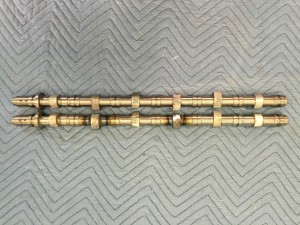
Cam cores done!

IMG_0573


Had a problem with my 3D model for the lobes. I didn’t catch it until it messed up 2 lobes. It was right on the edge of not needing a weld but I figured better safe than sorry.

They are boxed up and heading to Isky today. 6 days to get there, 6 to 8 weeks to grind, 6 days back. Now I know how my customers feel:)

I’ve got plenty to do. The manifolds are on the way to me so I can get that all squared away. Then the valve cover.

Machining the cam lobes

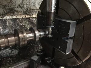
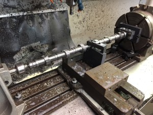
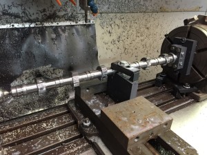
Got the 4th axis back up in the mill and decided it was time to do the lobes. My plan is to rough it out on one plane then rotate 90 degrees and rough again. Repeat at 180 and 270 degrees. I’m hoping there is enough material removed at that point to go straight to the grinder.

First step key slot.

IMG_0563

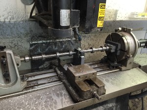
After this is done I have a fixture that clamps on the front and keeps the cam indexed to the 4th axis.

I machined a V block in line with the centerline of the cam and added a clamp. This is way too long to machine without a center support.

IMG_0564

First cut!

IMG_0565


This is after the first roughing pass. I’m using  .035 depth of cut which is leaving a bit of a step. I may make it a little less on the next cut. If I decide to do a finish pass that will all go away.

IMG_0566

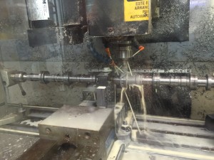
Here I’ve rotated it 90 degrees. I also rotate it in my CAM program so it’s looking at it from the new direction when I calculate the new code.  4th axis work can be tricky if everything isn’t setup properly.

IMG_0568

Well that’s it until Monday.

Got The Head Back From Mazworx

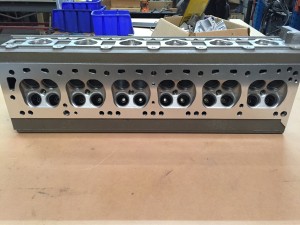
Starting to look like a finished product.

IMG_0547


I was really happy to find out when I dropped the head off to find out that Jim Thompson formerly of Sunbelt Engines is now doing head work at Mazworx. He did all the work on the head. I wasn’t in a position to post about it then as I didn’t get his permission to mention it. It really felt good knowing “an old hand” was going to be doing the work.

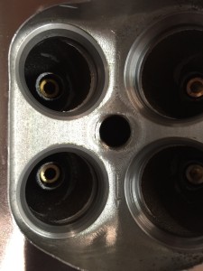
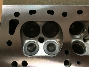
I knew there was going to be a little bit of an issue with the exhaust seats as I had to move the valves from their original position. There is a step on one side that I can blend and a ledge on the other side. None of us feel it’s going to be a problem for this build. The next design will have a smaller as cast seat area so there will be more meat.

IMG_0550

The other issue is for some reason I felt it was a good idea to put a boss inside the port for the valve guides. They won’t be in the next gen either. There is plenty of meat for the guides without the bosses.

I’ve waited a long time to see this:

IMG_0549

Let’s Talk Camshafts

Camshaft development took place at multiple times over multiple months so I decided to condense it into one post.

I started out thinking I would call any of the Honda K20 cam mfg that offered “custom cams” on their web page and have a 6 cylinder version of one of their cams made. Well custom means custom grind. If you don’t have the core then they cant do the grind. So I went in search of having custom cam cores produced. There aren’t too many core manufacturers out there and even fewer that will talk to a privateer like me. The best price I got was like $2800.00 for 2 cams if I bought them in quantities of 8. And this was just for the core. It would still have to be final ground.

I then proceeded to educate myself about cores. I indirectly work with a steel foundry that pours 8625 steel. I decided to give that a try. I made a set of patterns and had 2 sets of cams cast. I wasn’t happy with the results. I discussed the issues with the foundry and ordered another set. While I was waiting I started to listen to all the people on HybridZ that recommended I machine my own cores out of 8620 round stock. I bit the bullet and ordered a 20 foot length of 2″ round.

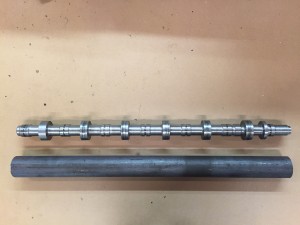
Before and after. From 22 lbs down to 7 lbs
IMG_0543


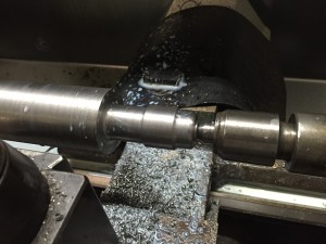
Started out by turning down the entire OD and then The back end
IMG_0533

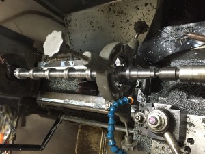
Then I flipped it around and started a carvin!
IMG_0537


Next up will be cutting the lobes in my mill