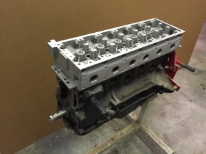
Front Section Machining

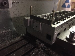
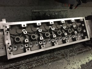
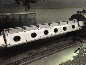
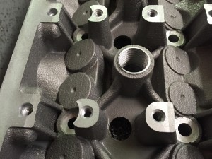
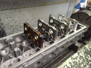
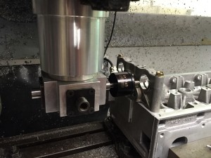
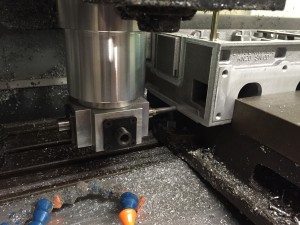
Machined the front of the head. I knew this was going to be a PIA from the word go. I just don’t have a proper angle milling head to really go at it.

I bought a used angle head on ebay a few years ago. It’s designed for woodworking but it was cheap so I went for it. In the first shot I’m using the probe to indicate off of the cam bores.

IMG_0310

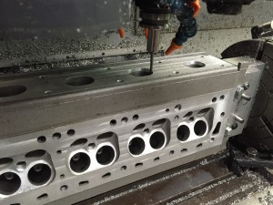
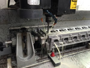
Here I’m surfacing the front of the head. The finish came out a lot better that I expected considering the rigging I had to do to make it work.

IMG_0311

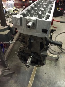
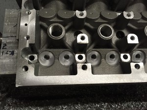
Faced the upper timing chain tensioner and the upper chain idler mount, spot drilled the timing cover and tensioner holes. I’m going to drill and tap those manually as I didn’t have anyway to hold drills in that angle head. No biggie.

IMG_0312

Got lucky on the pilot bore on the idler mount. You have to tap it on with a plastic hammer.

IMG_0315

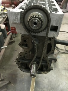
The chain fits well. I knew I was going to make a spacer set for the bottom gear since it’s a single not a double like the stock chain. The single chain tracks along the center of the guides now which is what I was looking for.
IMG_0316

X-ray results

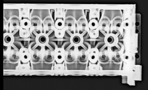
Got the head back from X-ray on Saturday. No big surprises.

Here is a shot of the front half

rad2_zpshzqv1wte

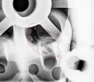
Here is a closeup of a known shrink porosity problem.

rad1_zpsrvmsuoes

I knew it was there because you can see it from the top. I wanted to leave it to see what it looked like in the X-ray. You can see it leads all the way over to the valve guide bore and in fact you can see it in the bore. I’ll do a weld repair on the top and call it a day as it’s too small a defect to affect the valve guide.

Controlling solidification shrinkage is one of the tougher aspects of casting metal. We’ll try something a little different on the next one.

Every head will be x-rayed before they get sold. This way people can have confidence in the casting before they invest in machining.


Intake Valve Guide Work

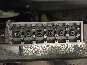
Got all the intake valve work done.

IMG_0284

Got a little carried away with the machine allowance on the intake side! Had to take it down almost .375″.  I had to leave that wall around it because the mill was hitting the side of the head. You can see where it nicked the intake bolt boss.

IMG_0286

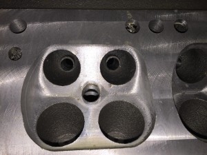
Every port looks just like this. Man I like digital mold making. The accuracy is just amazing.

IMG_0288

Exhaust Valve Guide Bores

Well today was a big and stressful day. I got all of the exhaust valve work done. Drilled and reamed the exhaust valve guide holes and machined the valve spring bosses.

IMG_0280

Everything seems to be working out as I planned.

IMG_0281

This is the best part. The bores came through right where I needed them to. After I had printed the sand molds I realized my valve angle was off by half a degree. That’s why the bore of the valve guide is not centered on the boss. Future heads won’t even have that boss on there. I’m not really sure why I put it in  as there is plenty of support for the guide without it.

IMG_0282

Exhaust Ports

Found time to map out the exhaust ports. They were all within .005″ or .006″ of where they should have been. A lot of that may have been the toughness of the casting affecting my touch probe accuracy. I can tell you that is pretty accurate for a sand casting.

Here is a shot of me taking a skim pass for port matching to the flange.
You can see I have a little hand work to do on a couple of the combustion chambers.Exhaust

IMG_0257

Exhaust side all done

IMG_0258

Tomorrow I start on the valve guide bores.

So I got the top surface done.

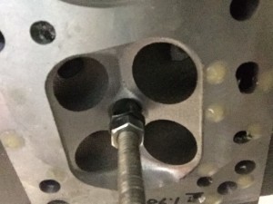
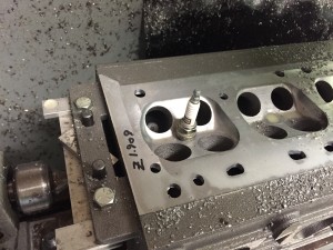
I started out with a modified spark plug stop to use as a gauge. I used the end of the threaded rod that goes up through the head to touch off from. This let me know where I was in relation to the combustion chamber.

IMG_0248

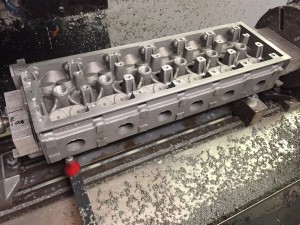
I surfaced the top,did all the cam tower work, spot faced the head bolt bosses, bored the spark plug tube bosses to the correct depth, tapped the bosses for the tubes and drilled the oil gallery.

IMG_0251

IMG_0254

Had to relieve one side of the cam towers for the ARP washers to clear.

IMG_0255

Set a few towers on for fun.

IMG_0256

Machining

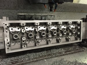
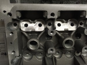
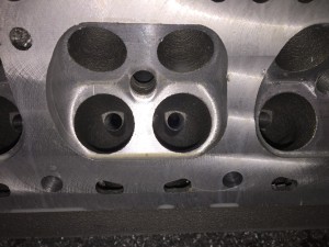
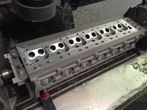
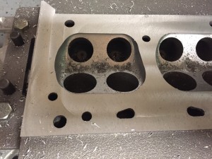
Made some progress today. Got the chambers mapped out and ran a finish pass over them. I designed the chambers to be “as cast’ but I knew that was a mistake as soon as I saw the casting. Since I didn’t have any machine allowance to work with I did the best I could. There are a few spots I’ll have to hand work. I finished the surfacing and recut the water passages to make sure they were in the right spot. They were off a hair. Really happy with the quality of the casting so far. I engineered the gating system to prioritize the combustion chambers and bottom of the head. The metal is super clean so far.

IMG_0239

IMG_0238


I’m going to need a lot of piston clearance for this to work :)

IMG_0242

Deep drilling the head bolt holes. This stuff make my butt hole clench.

IMG_0243

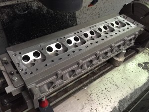
Bottom all done. (I think)

IMG_0246

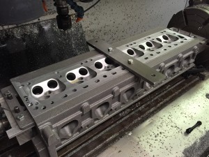
This is the ground flat bar that I’ll use to set the rotational angle when I roll it over. That way I’m indicating off of the bottom surface.

IMG_0247