New timing chain design

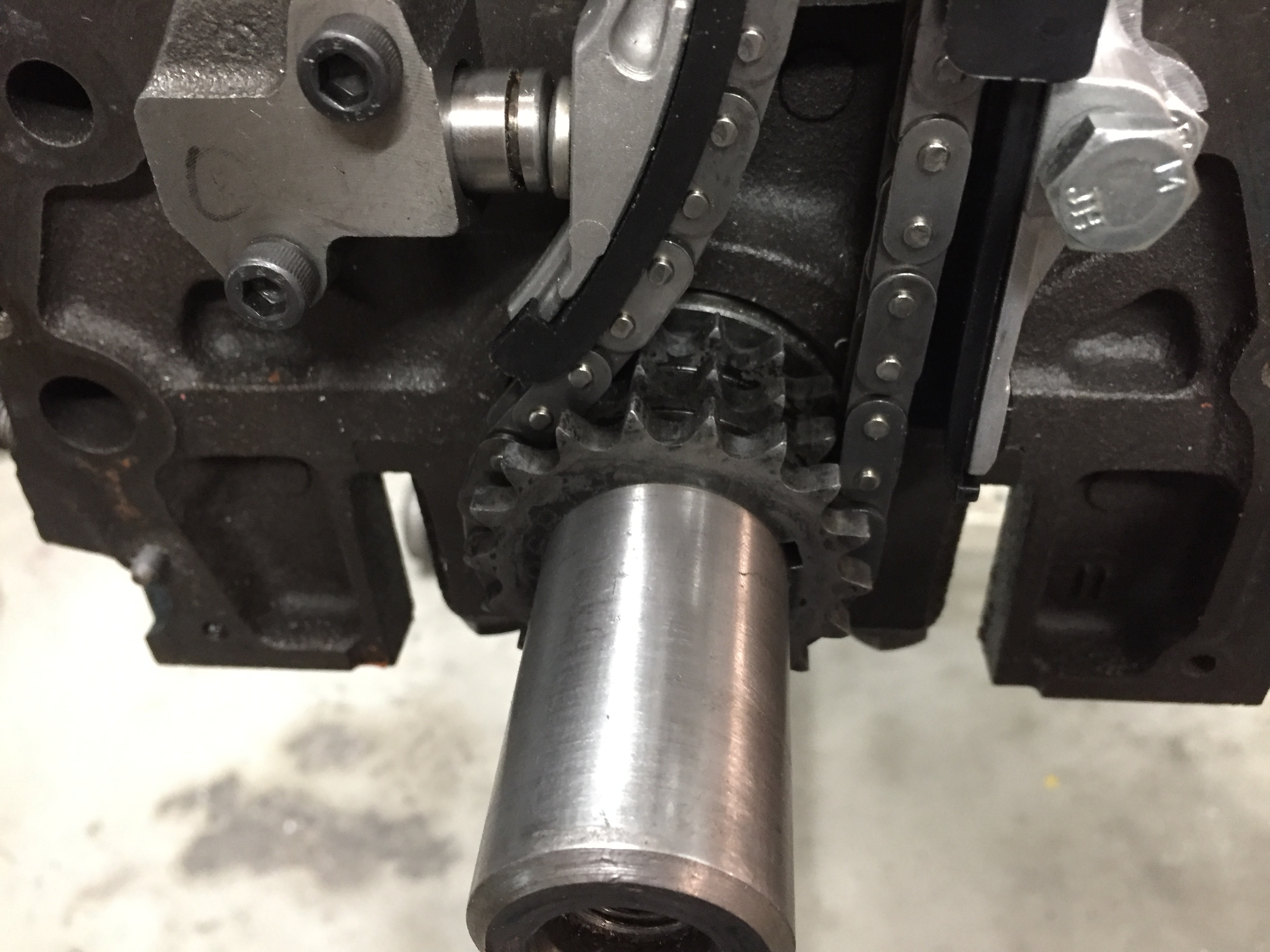
As many of you who have followed along for a while know the timing chain arrangement has been my White Whale since the beginning. I knew I wanted to use the KA24 timing chain setup and for the most part I was able to make that work. The problem was there just wasn’t enough room to fit the pivoting slack side guide and have it pivot at the bottom like it’s supposed to. The compromise was to pivot it at the top, use a custom guide and use the bottom tensioner in the stock L6 position.  This worked but the custom guide had to be a little thin in one area to clear the lower timing cover.   Now here comes a lesson for all you aspiring engineers out there and how solutions to complex problems can be incredibly simple.

I was speaking to Brian at Rebello after he finished the KN20 build they did for Z Car Garage. This was the first build they did for a sub 3.2L and they decided to use my system as opposed to the more complex system they designed for for the 3.5 motors. We were discussing the lack of room on the slack side for  the top pivoting guide and he mentioned that the KA24 heads have the idler gear pushed towards the tension side more than I had mine. I agreed this was worth looking into and set about manipulating the 3D model to see what I could make happen. I found I could pick up about 19mm by shoving the idler gear over. On the face of it a very simple solution to increasing the thickness of the pivoting guide. Problem solved. But wait it get’s better.

As I was sitting at my work station shoving various 3D components around to see what was workable I realized a fair amount of room opened up on the top and there may be room to squeeze a tensioner up there and have the bottom pivot guide I always wanted. I contacted Tioga who is my go to person for all things OEM and he got me info on the various available external tensioners that could possibly work. The problem was they were all too big to fit.

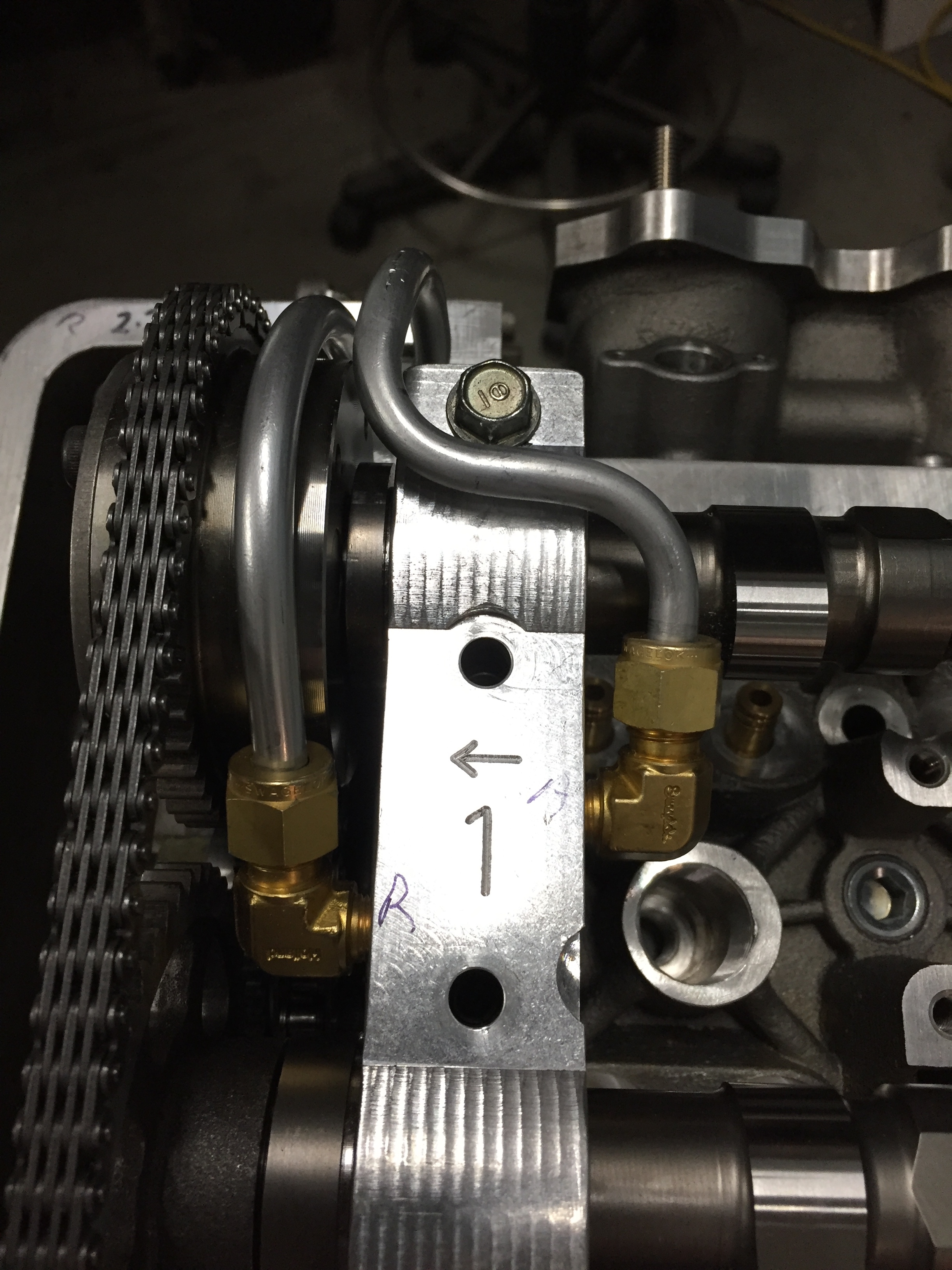
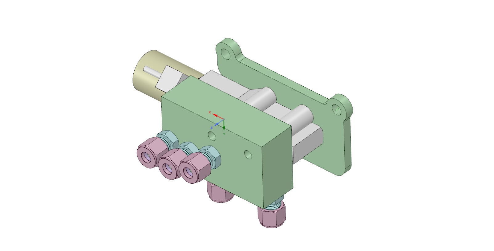
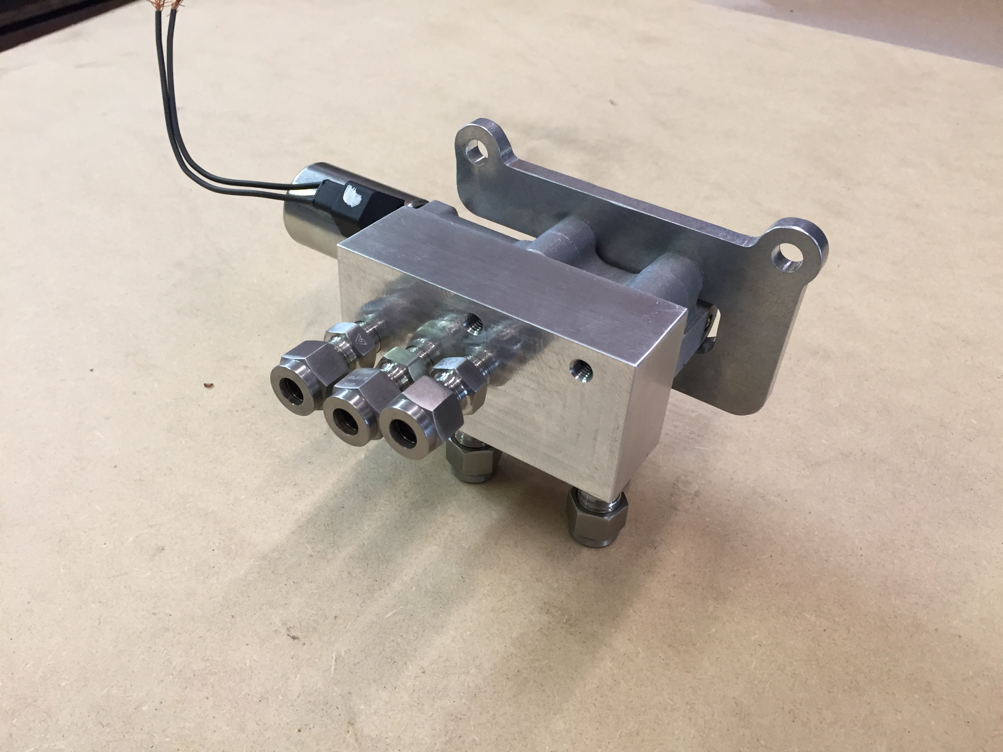
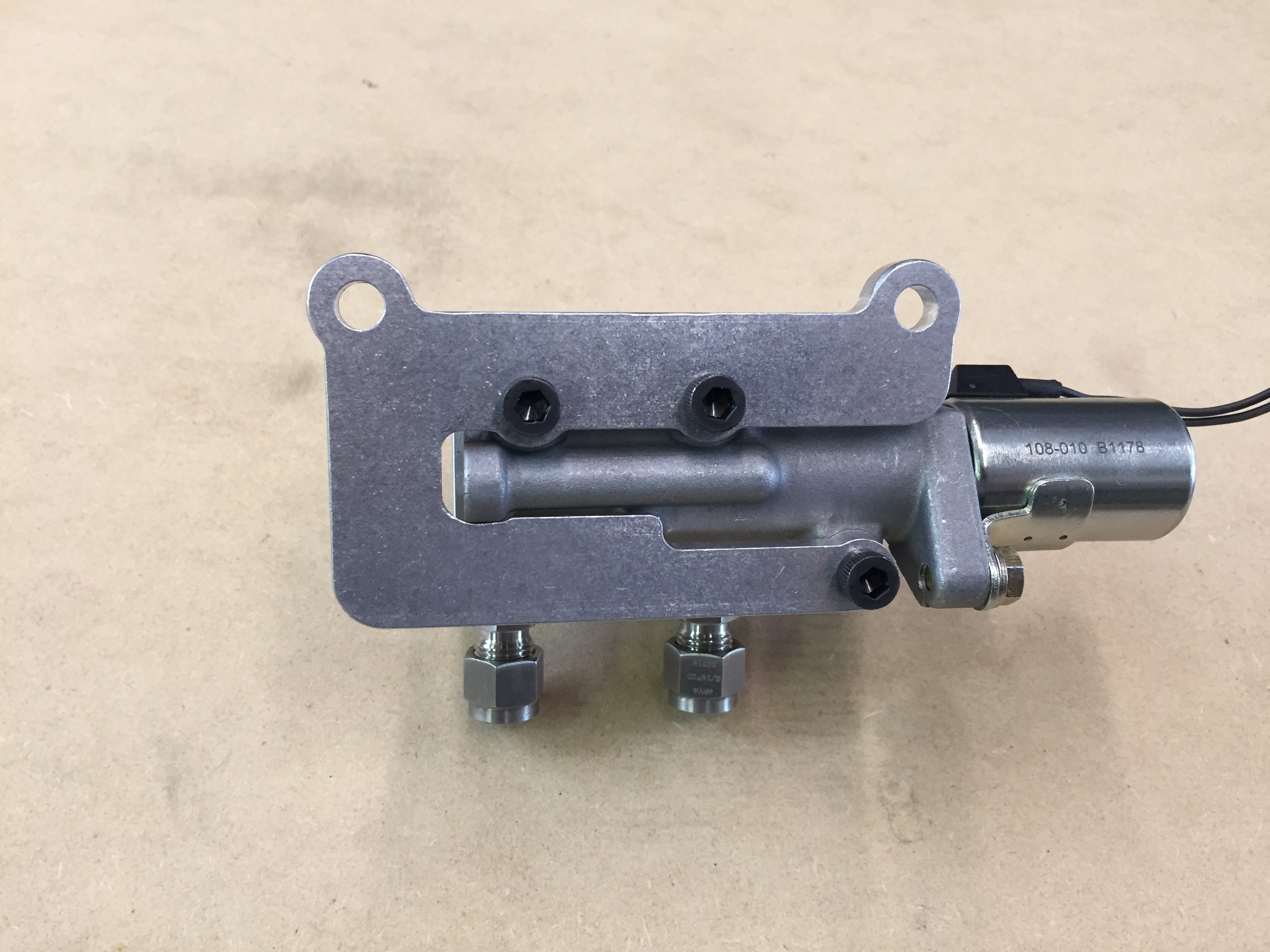
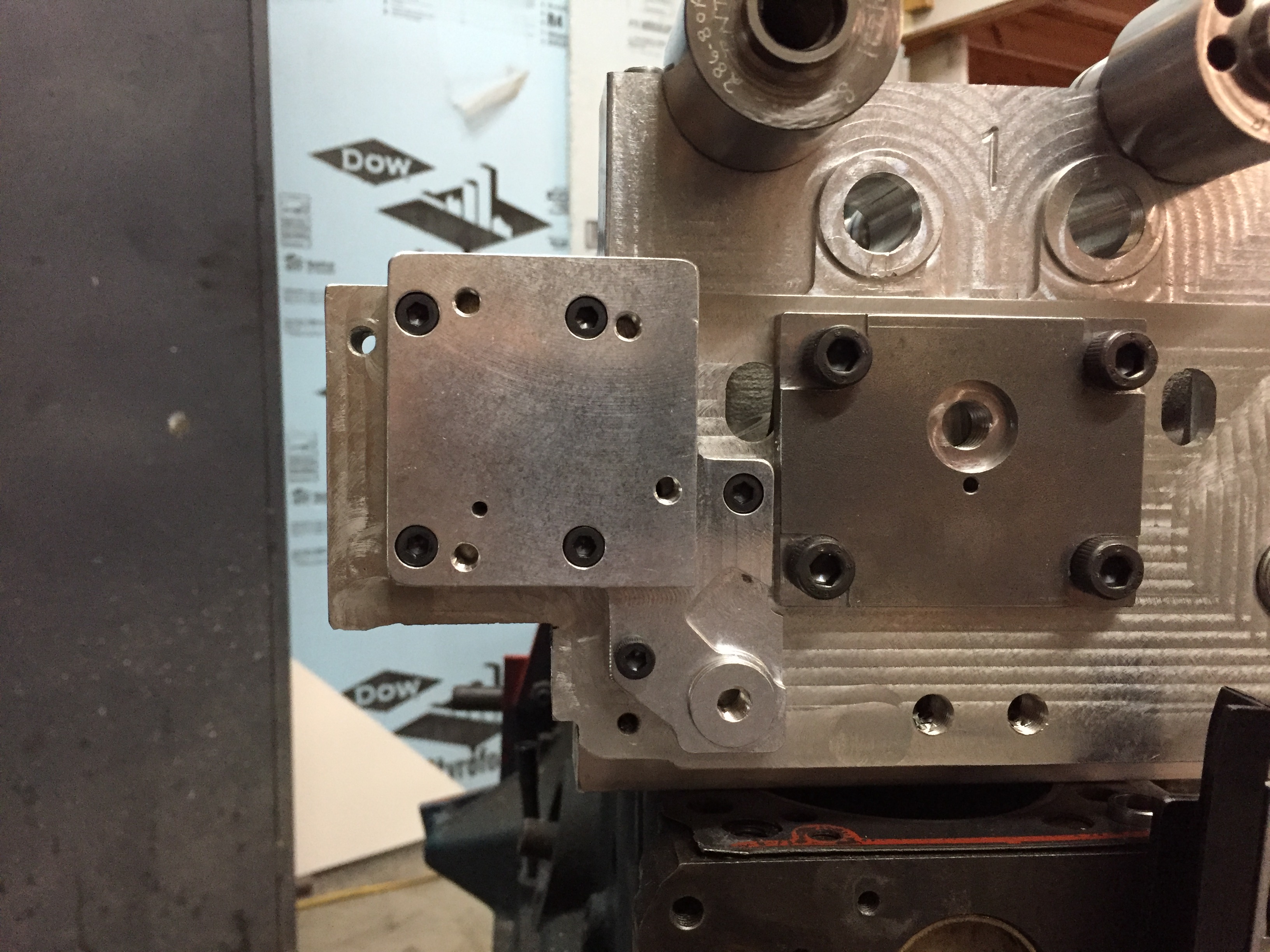
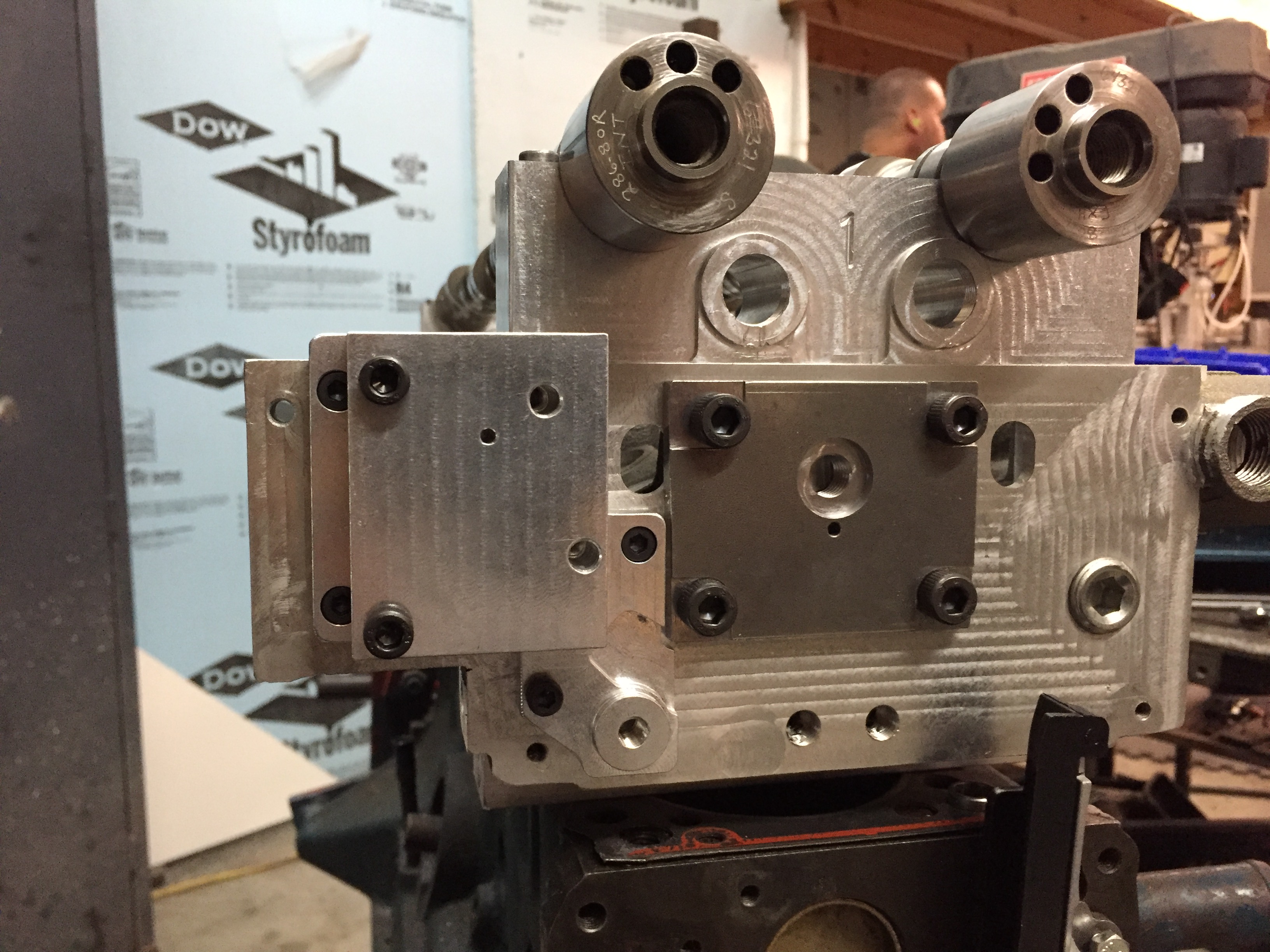
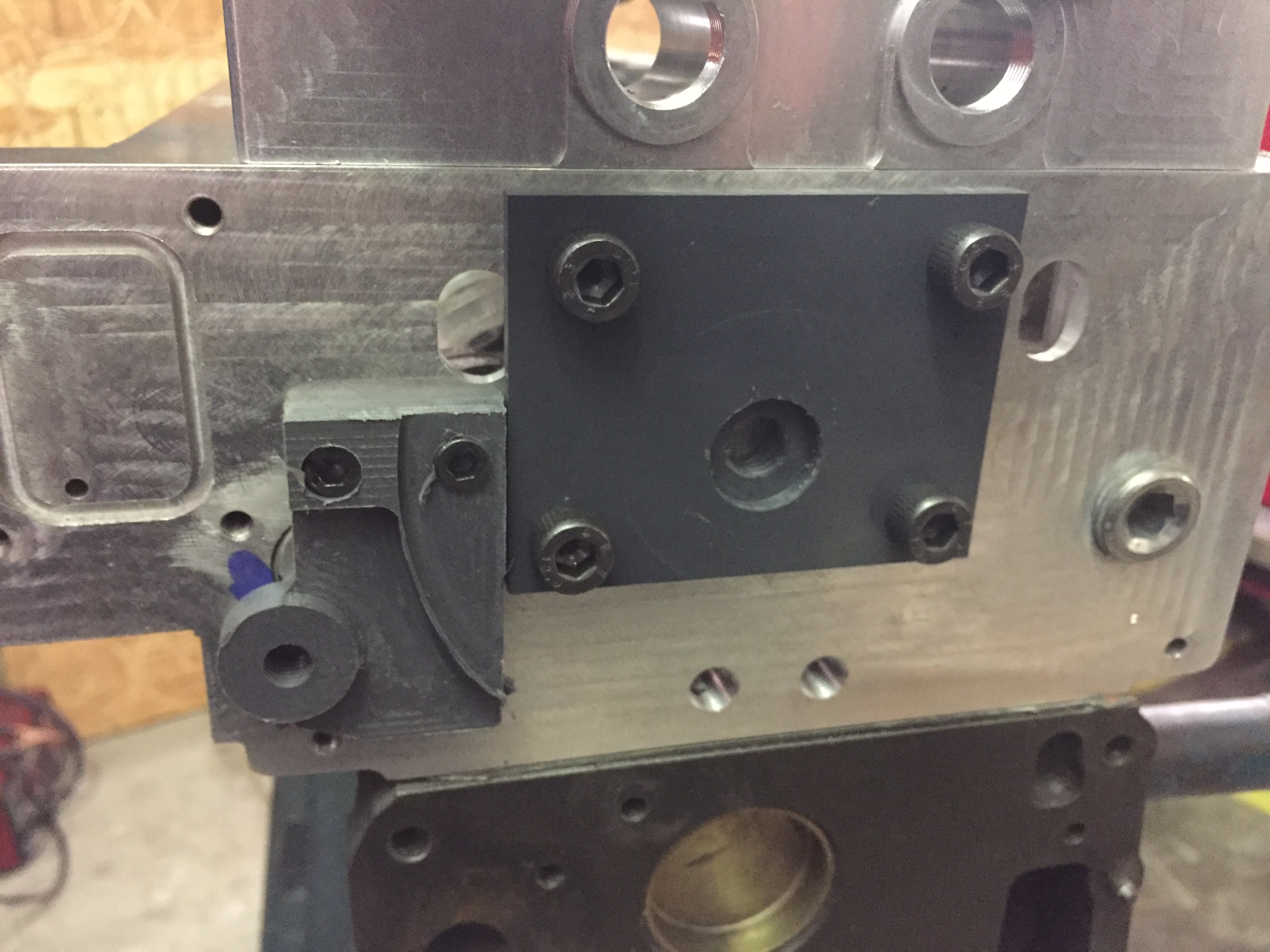
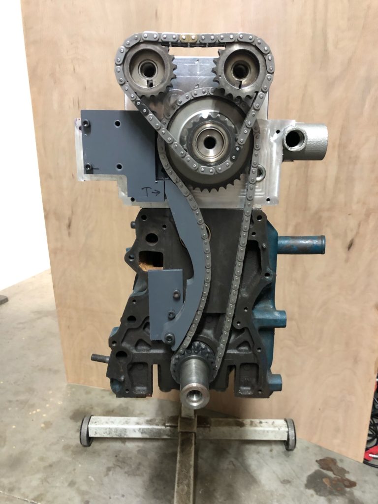
Then the epiphany. Why not design my own tensioner that will fit inside the existing available envelope.  Booooooommmm.  The hardest part was that I absolutely wanted it to retrofit to the existing heads I already had out there.  It was apparent that this would work and fortunately I had a head still here  so I set about with my tried and true mockup process. A little CAD/CAM add a little old school analog, bring the analog back to digital, rinse and repeat.  I ended up with this mockup. The letter T represents where the tensioner piston is.
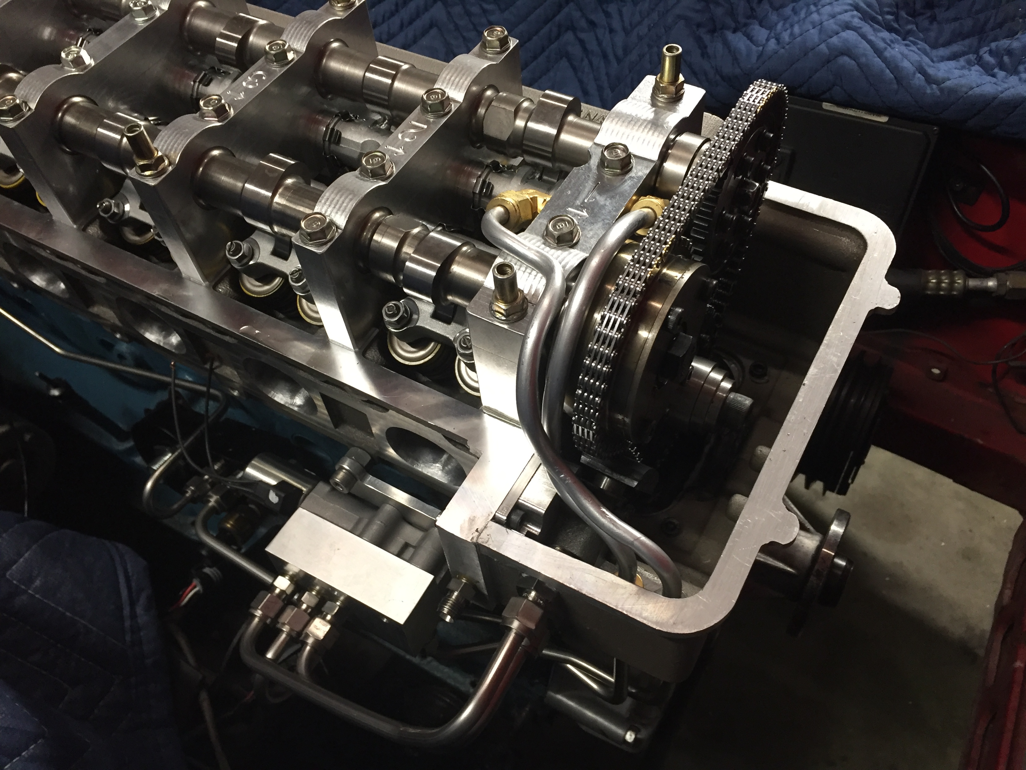
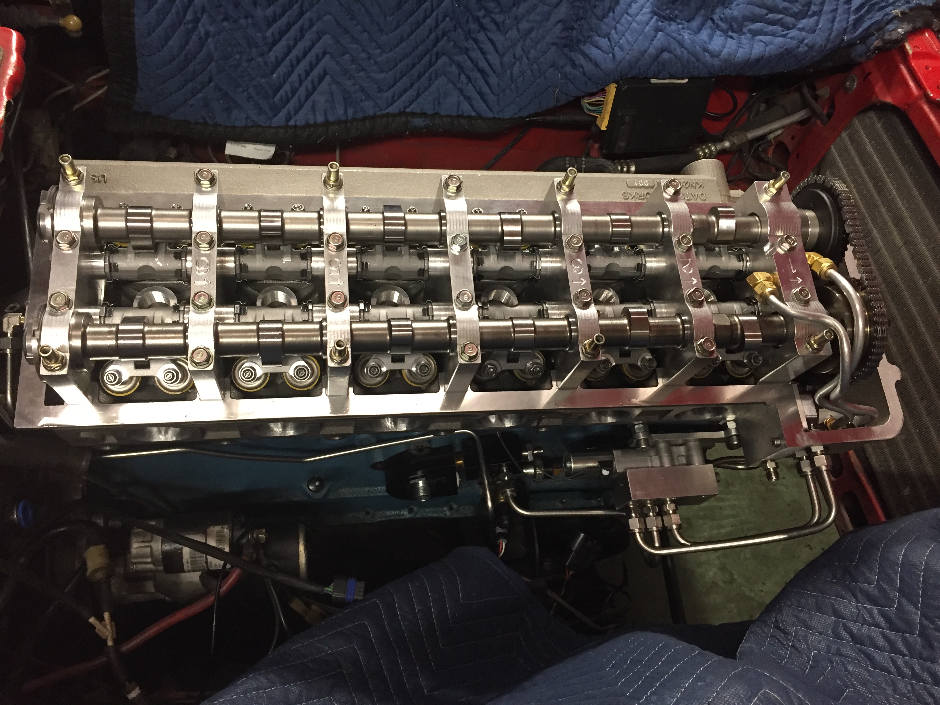
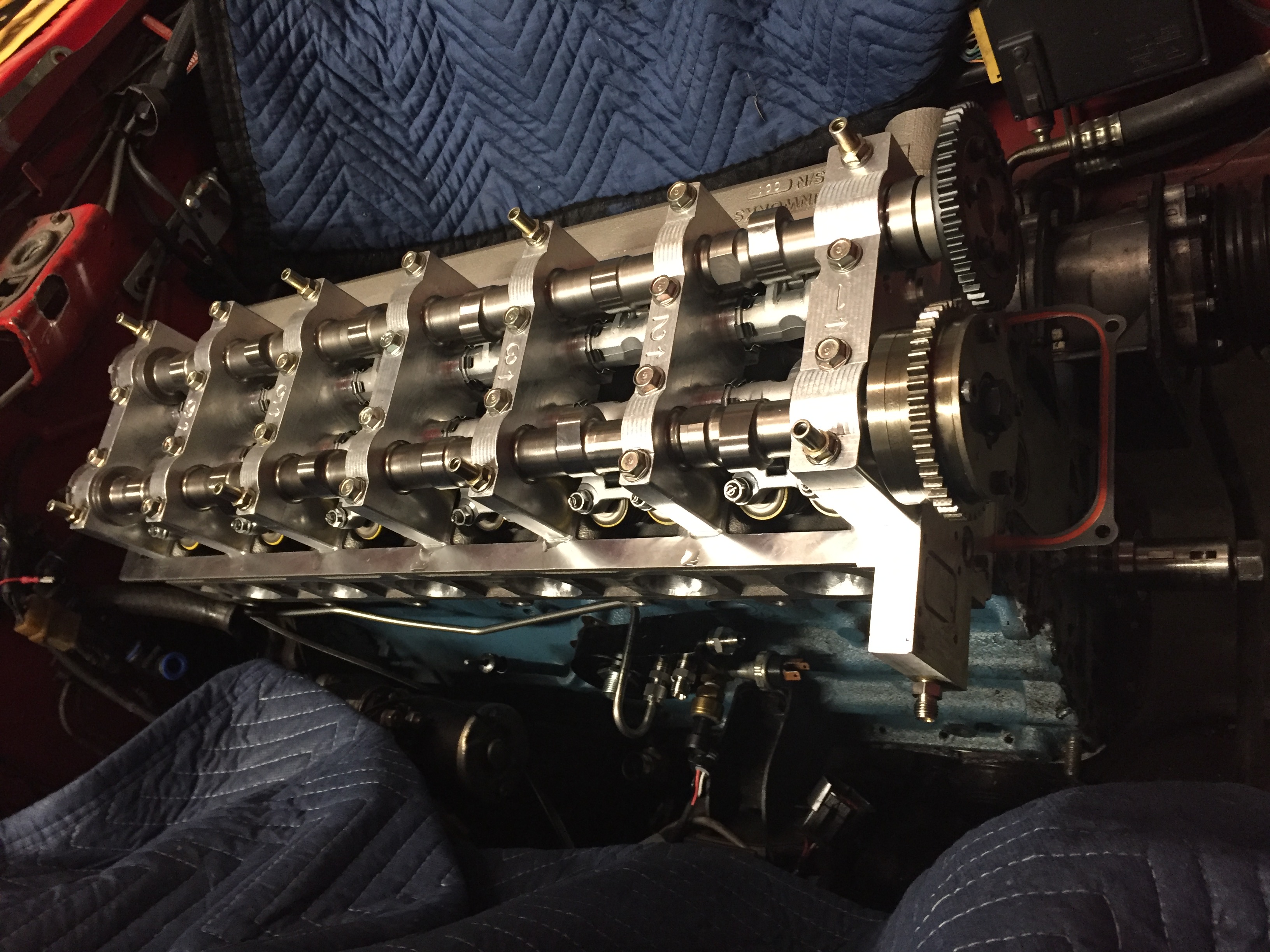
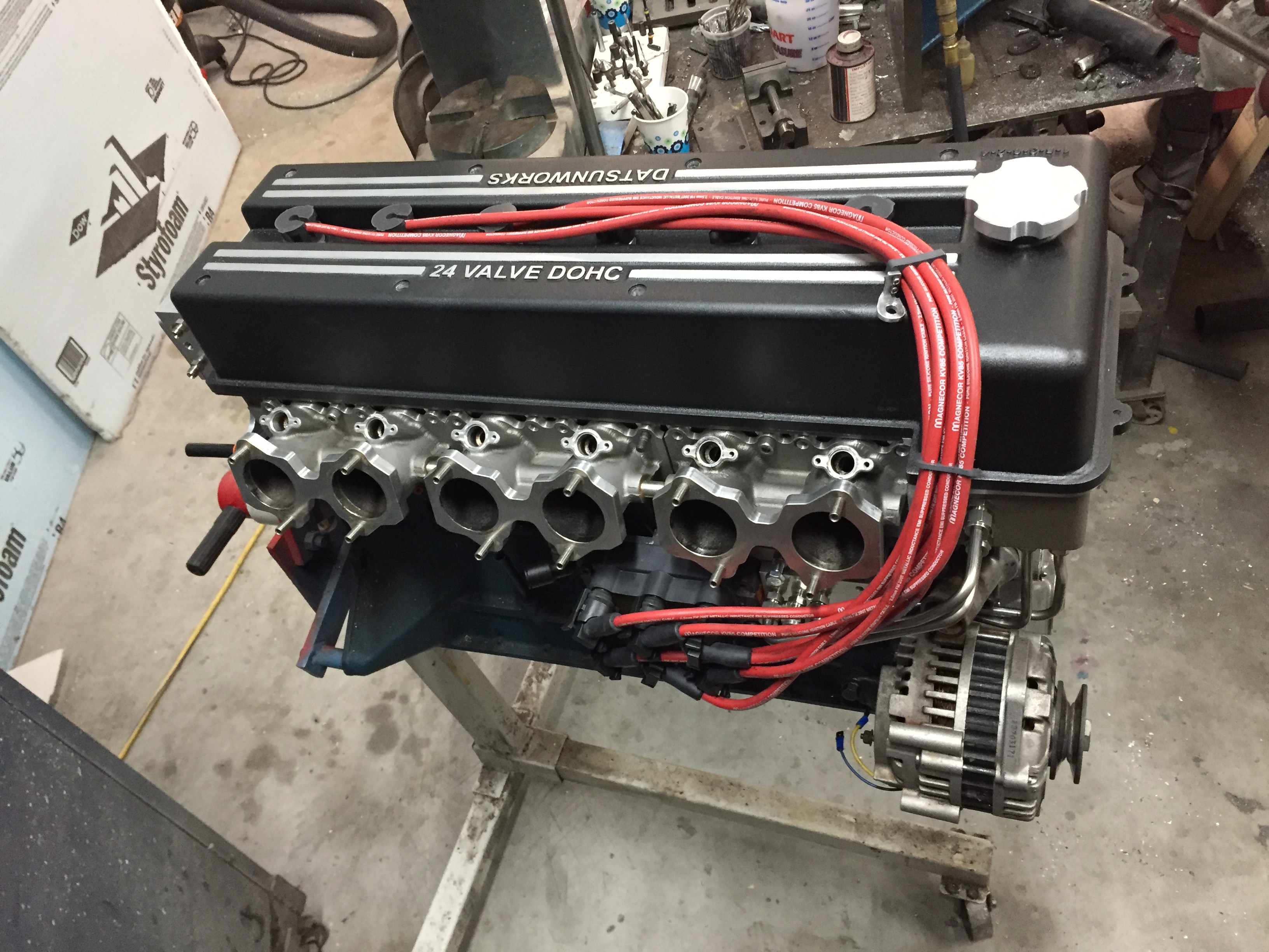
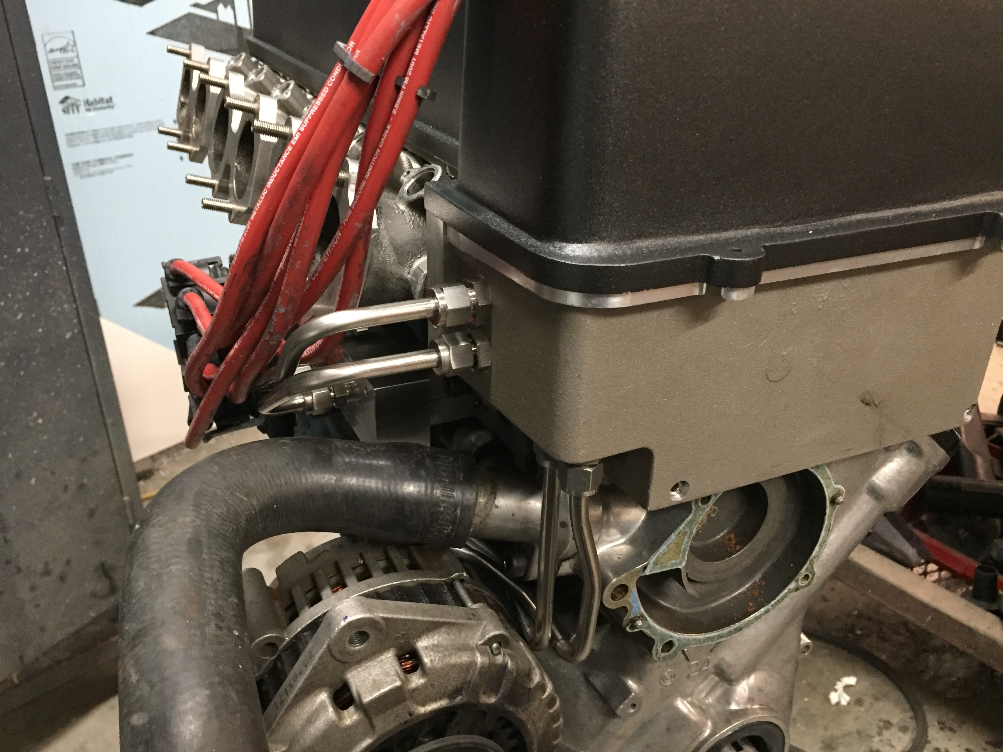
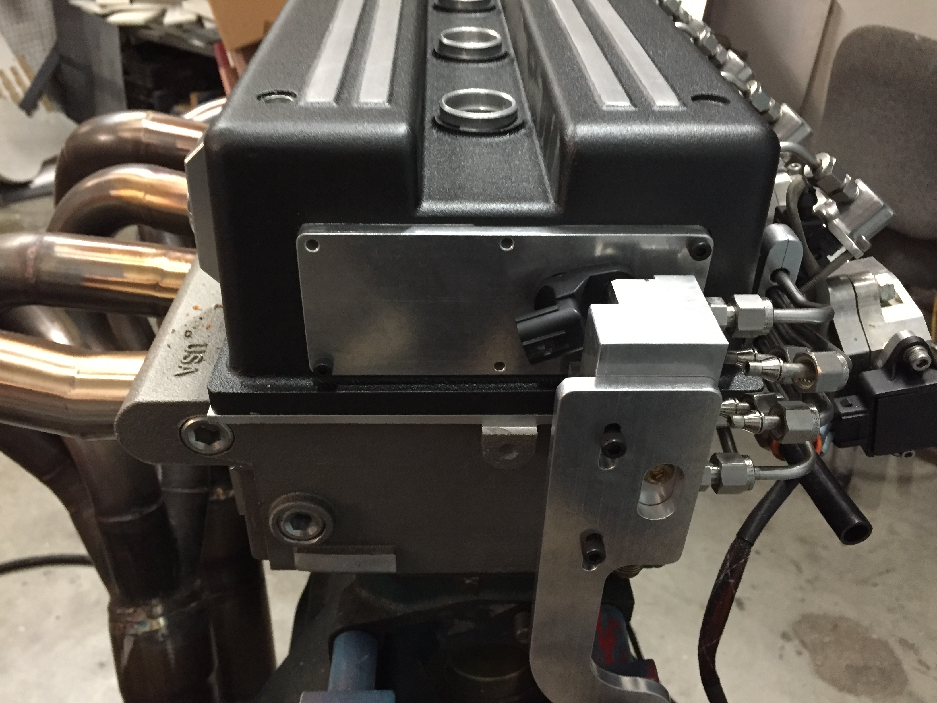
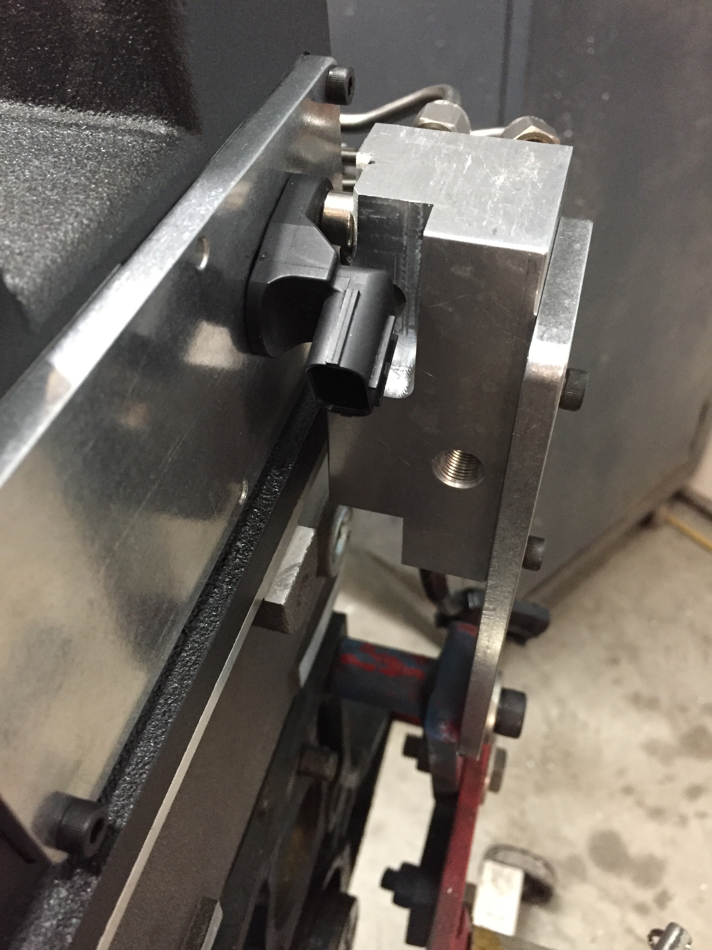
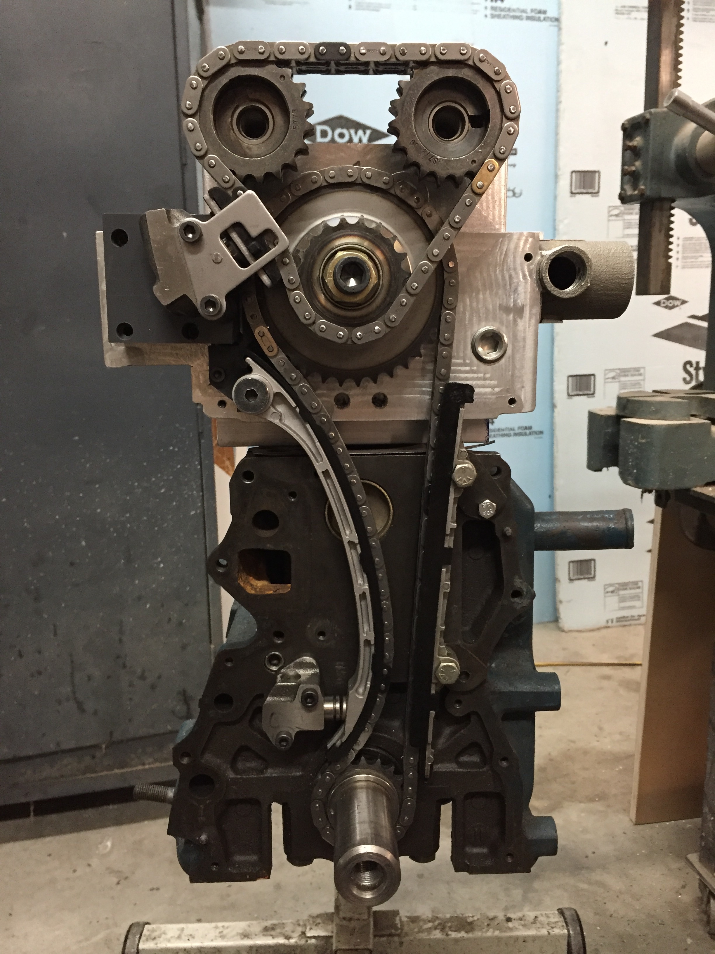
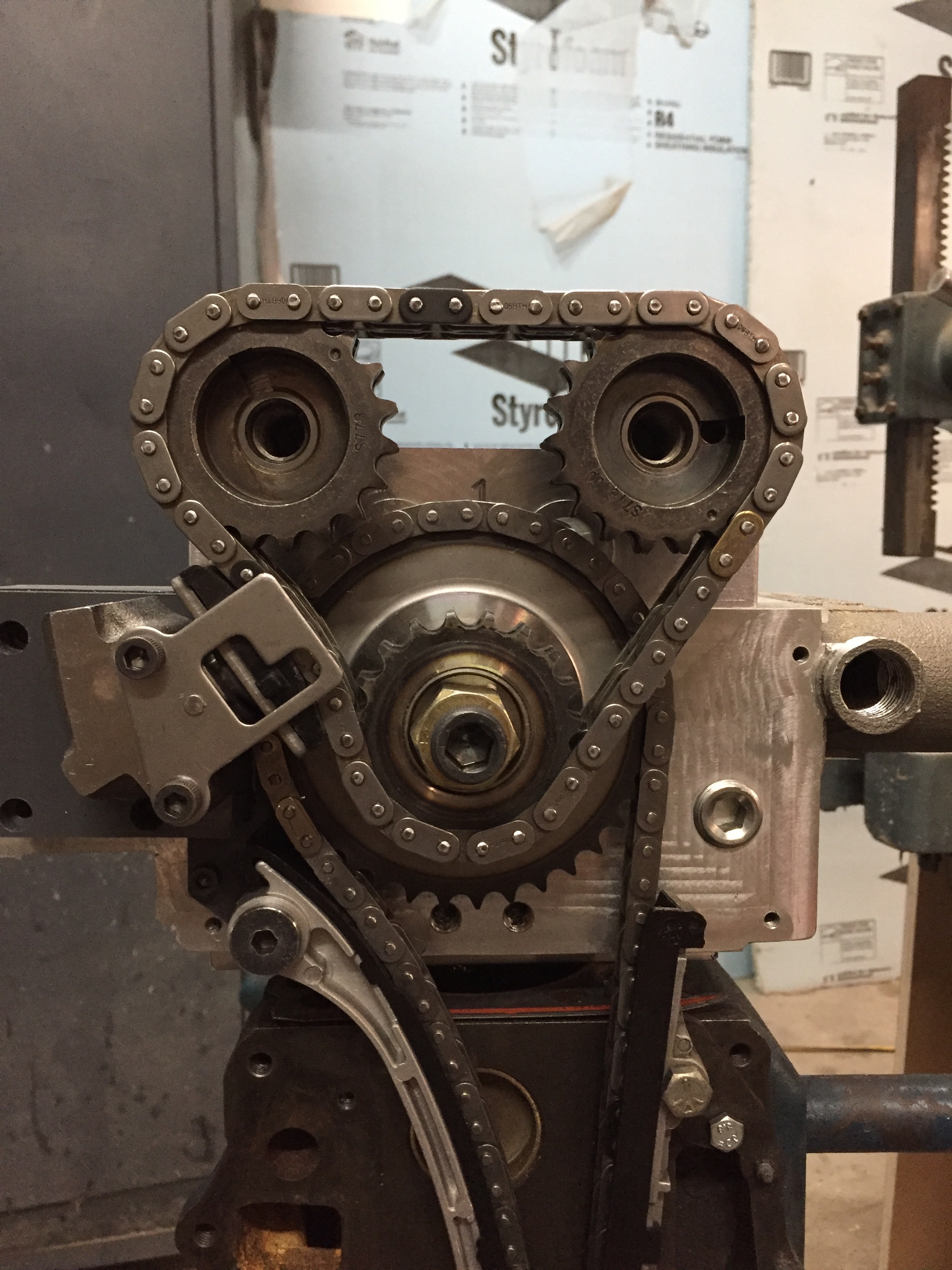
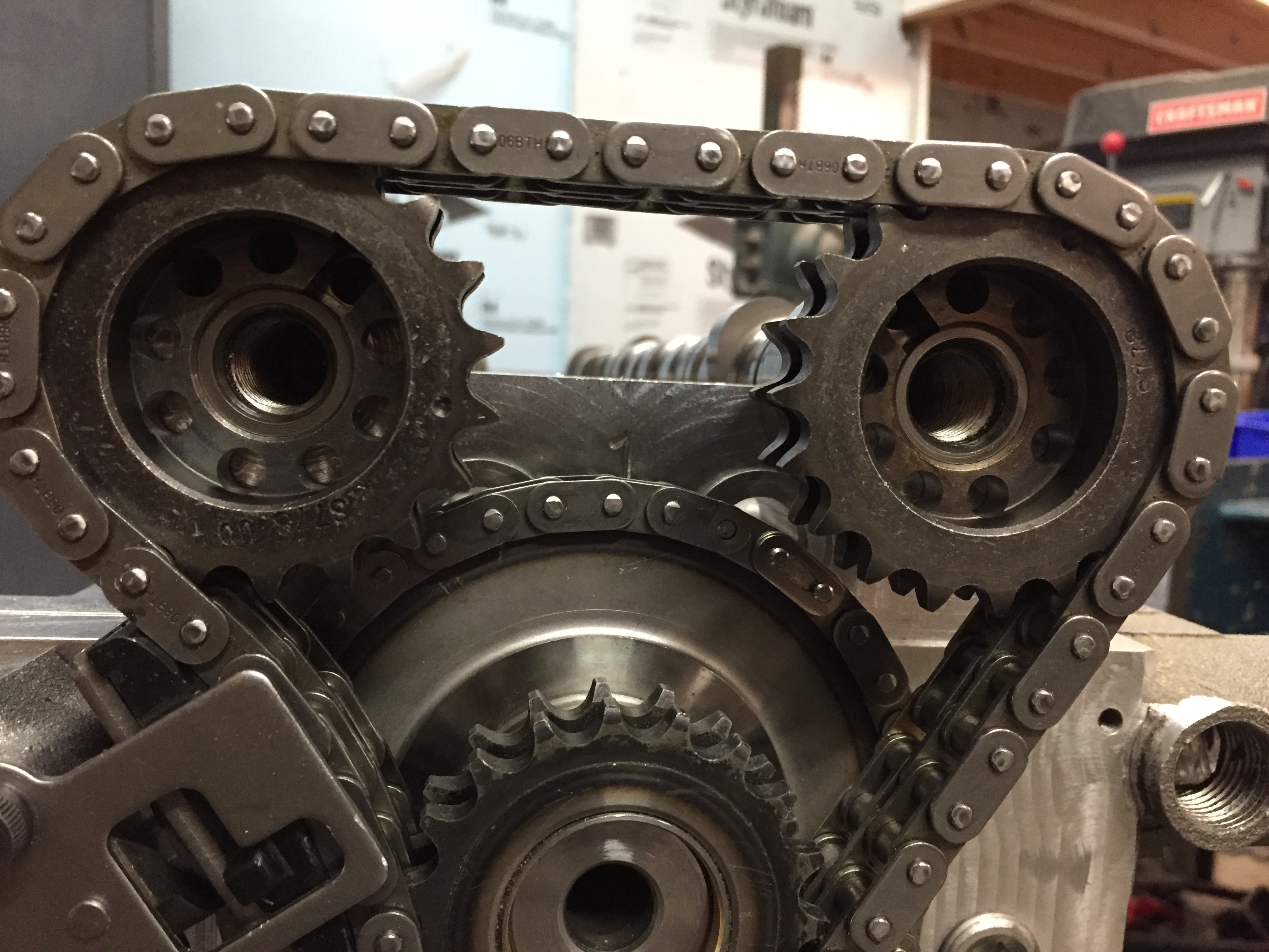
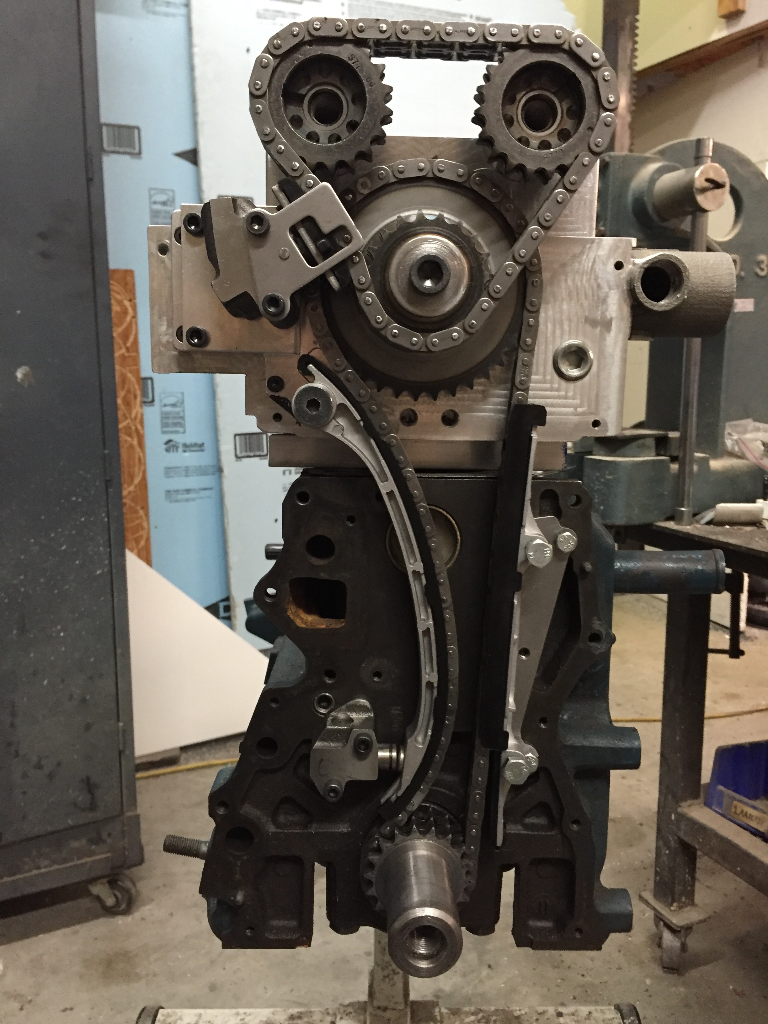
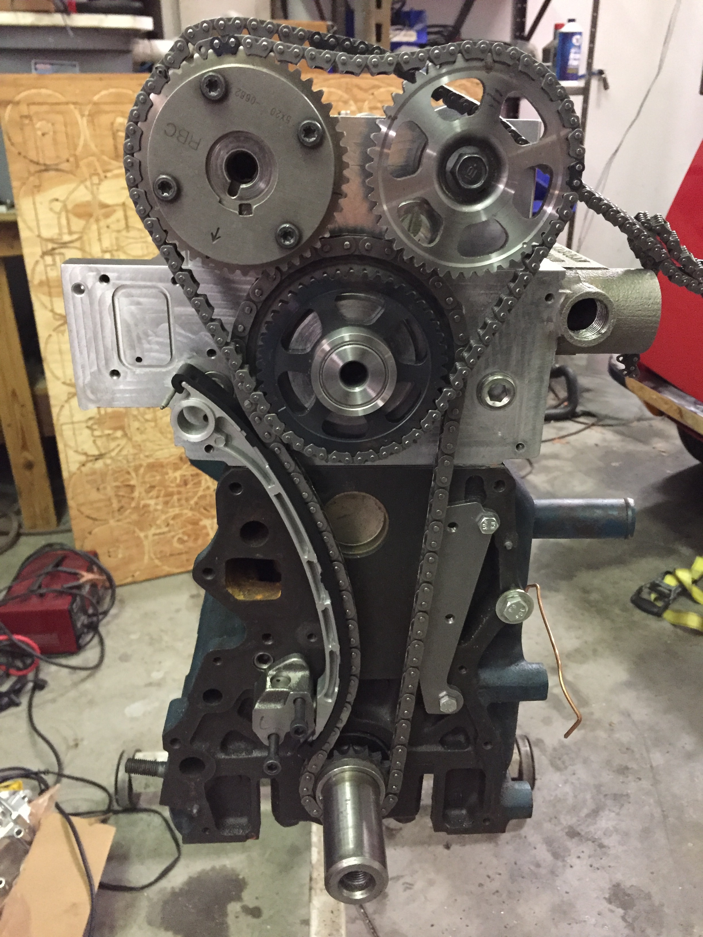
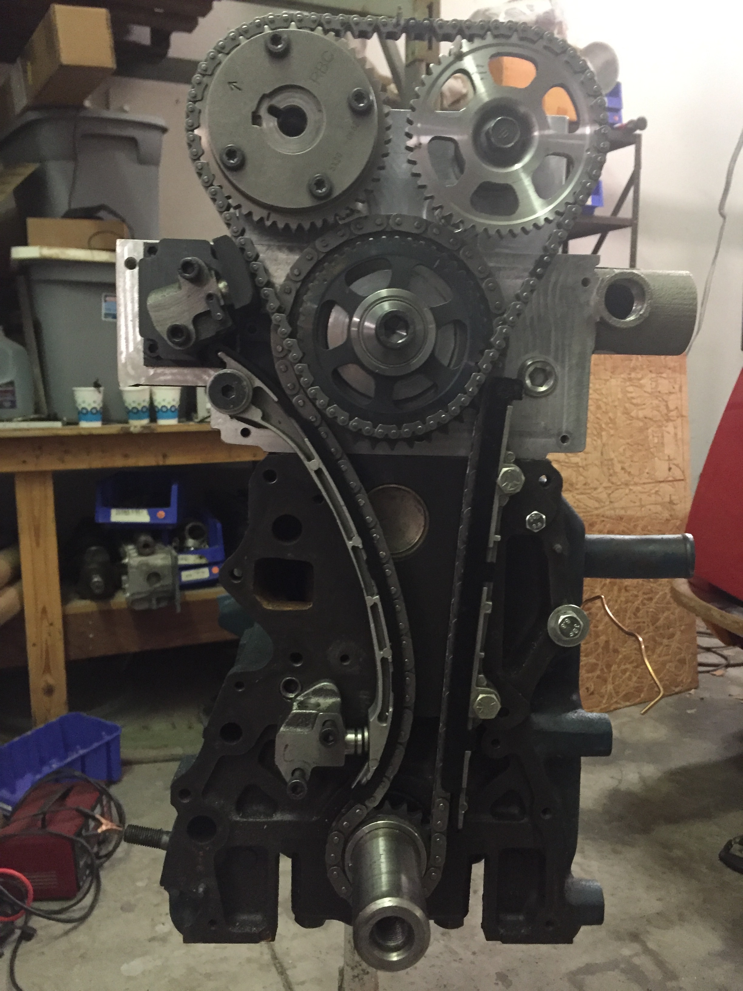
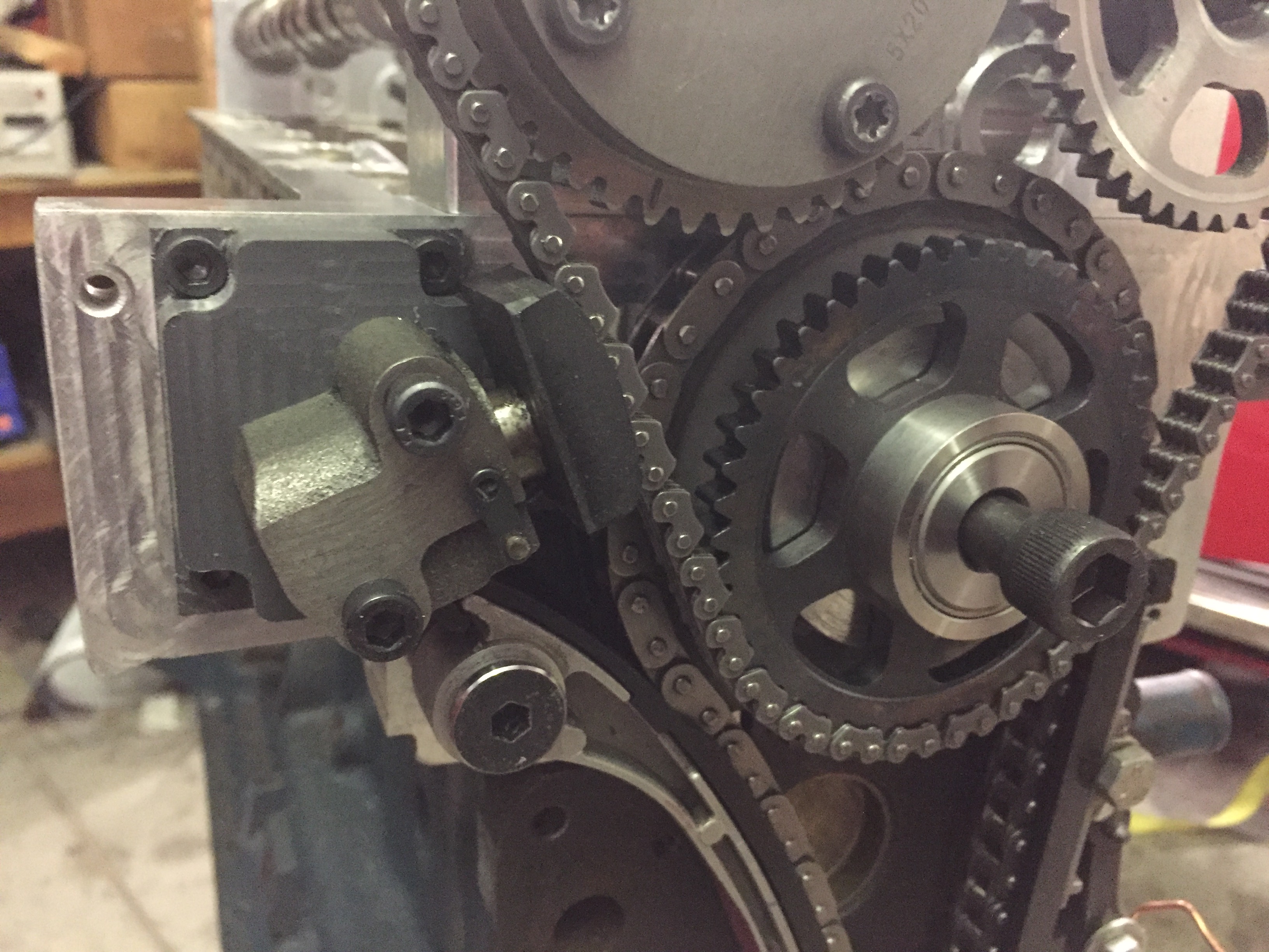
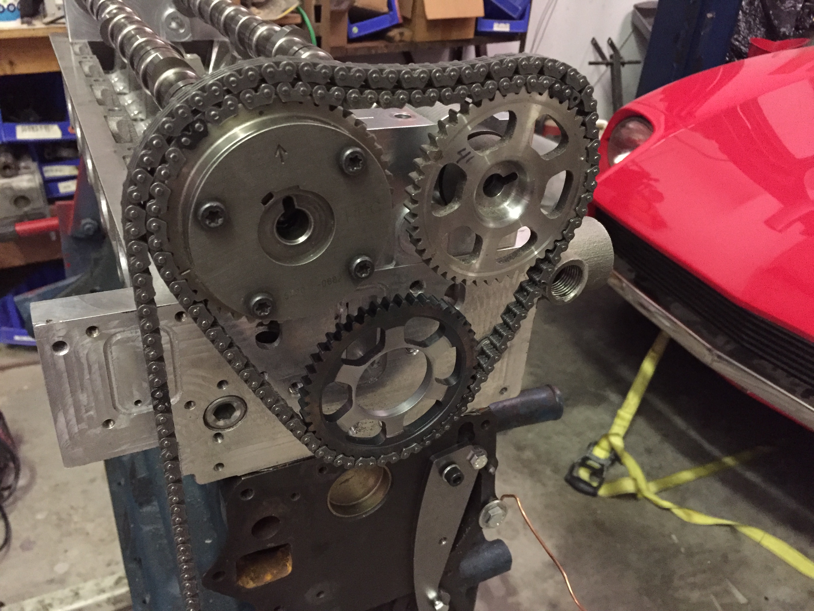
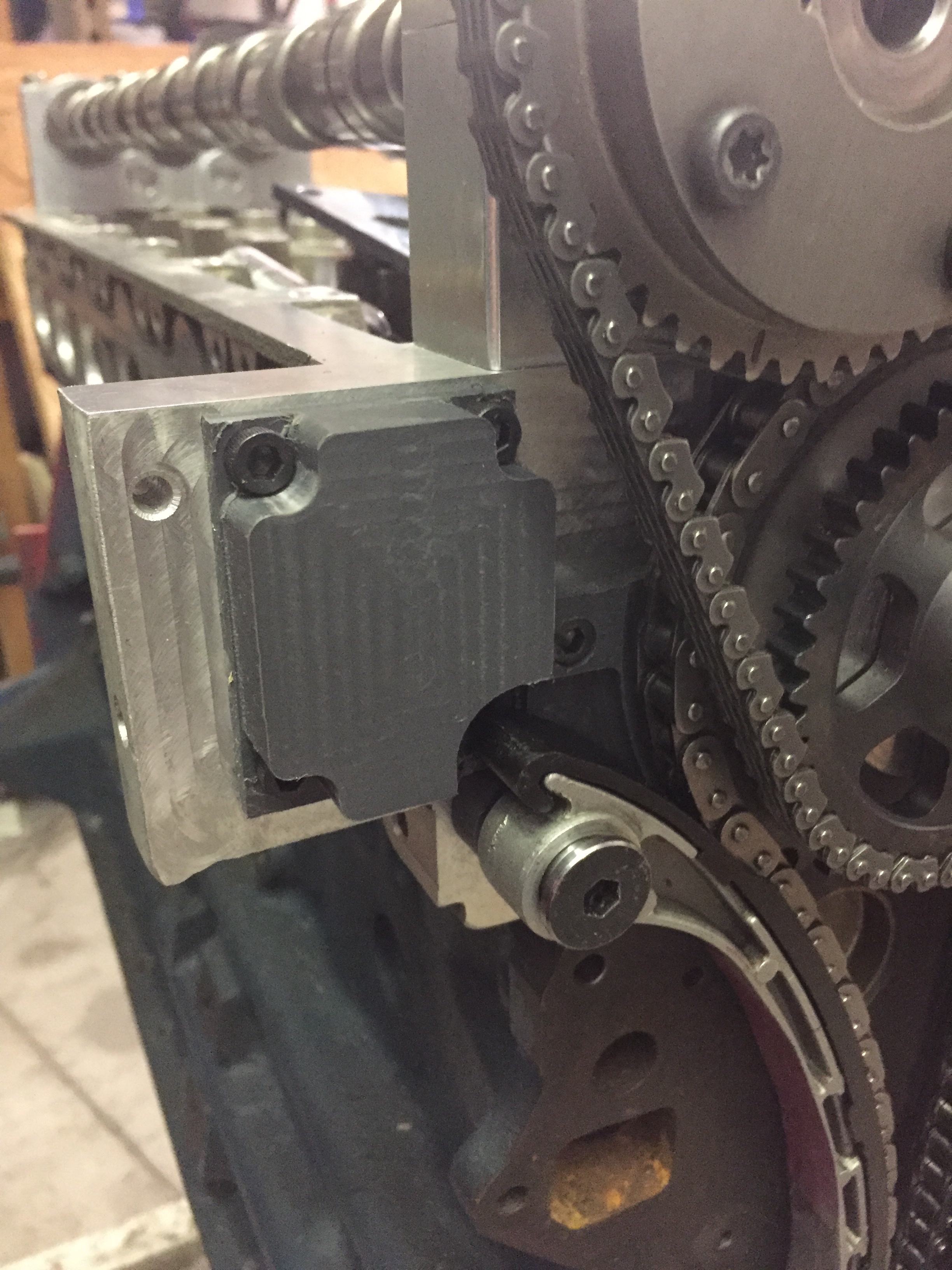
And here is the final product. The adjustable cam sprockets are from Tomei FYI and are really well made. The slack side guide is much more robust and the front lower timing cover fits without any modifications. The stock L6 tension side guide fits with some minor slotting and cutting. The chain angles and flow look great so I’m super happy with the outcome. 
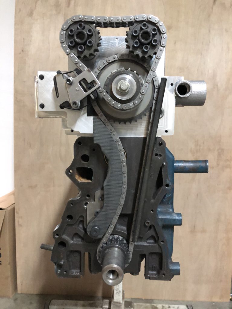
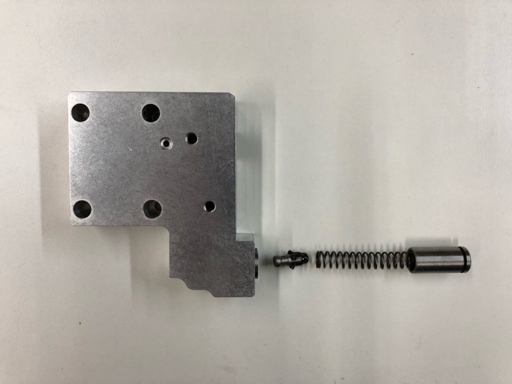
The tensioner is also the mount for the upper tensioner.  The slack side tensioner uses the piston, spring, and check valve from a KA24 tensioner. The body is 6061 aluminum with a 4130 DOM (drawn over mandrel) honed sleeve inserted as the cylinder.
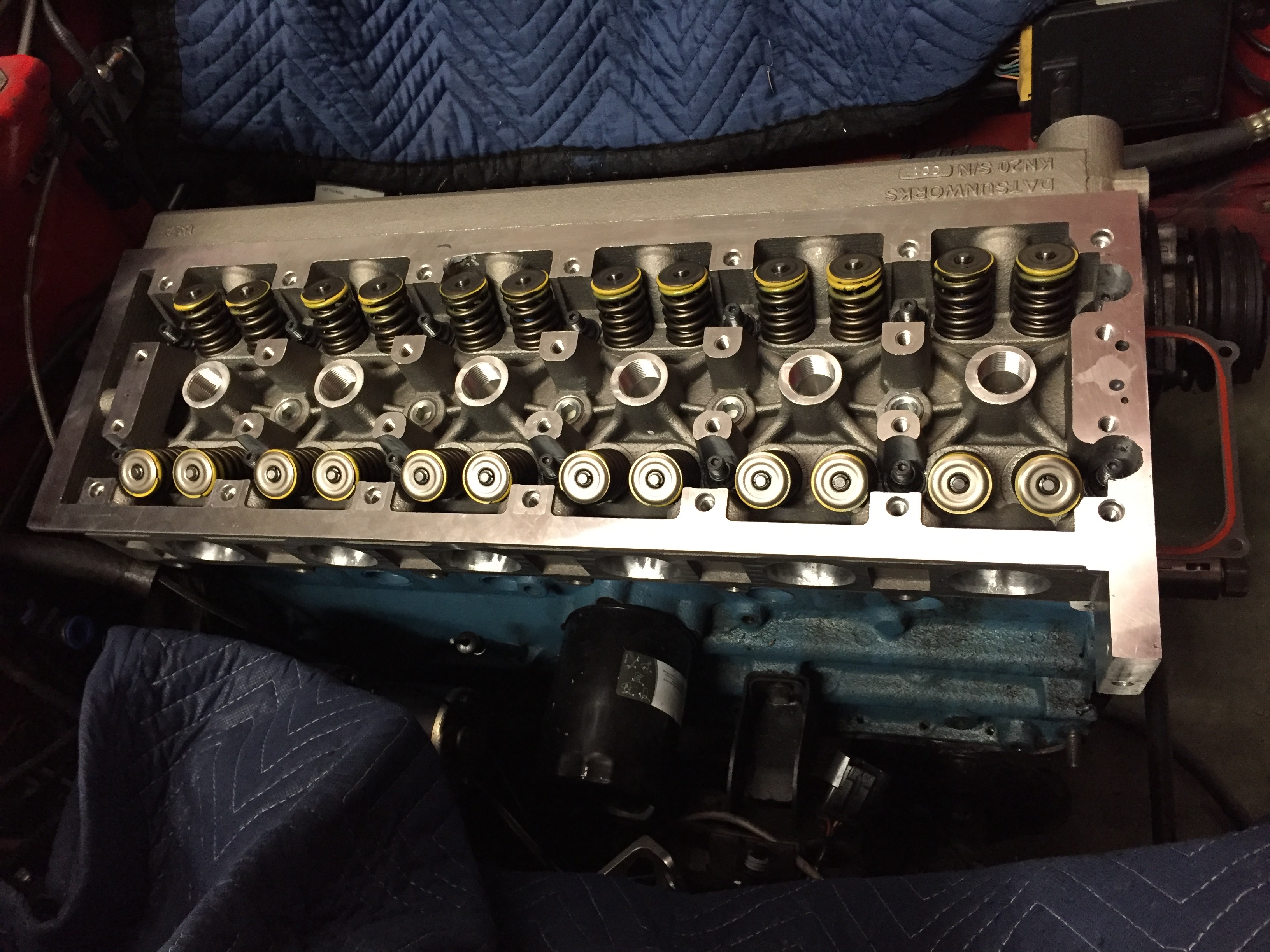
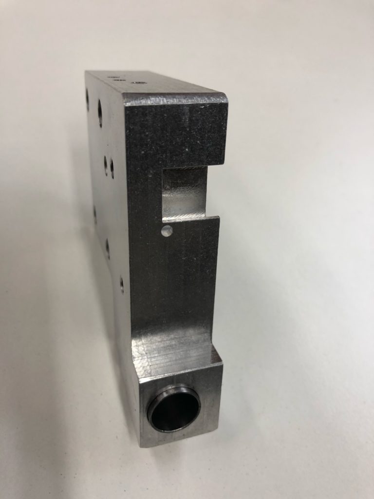
The front of the head has scuppers to drain the oil from the valley and the new tension block blocked the right one. I had to machine a drain into it and decided to include a dribble hole to help oil the lower chain. Probably useless and the KA24 upper tensioner pukes so much oil that I doubt the lower chain will ever run dry but I felt like putting it in.
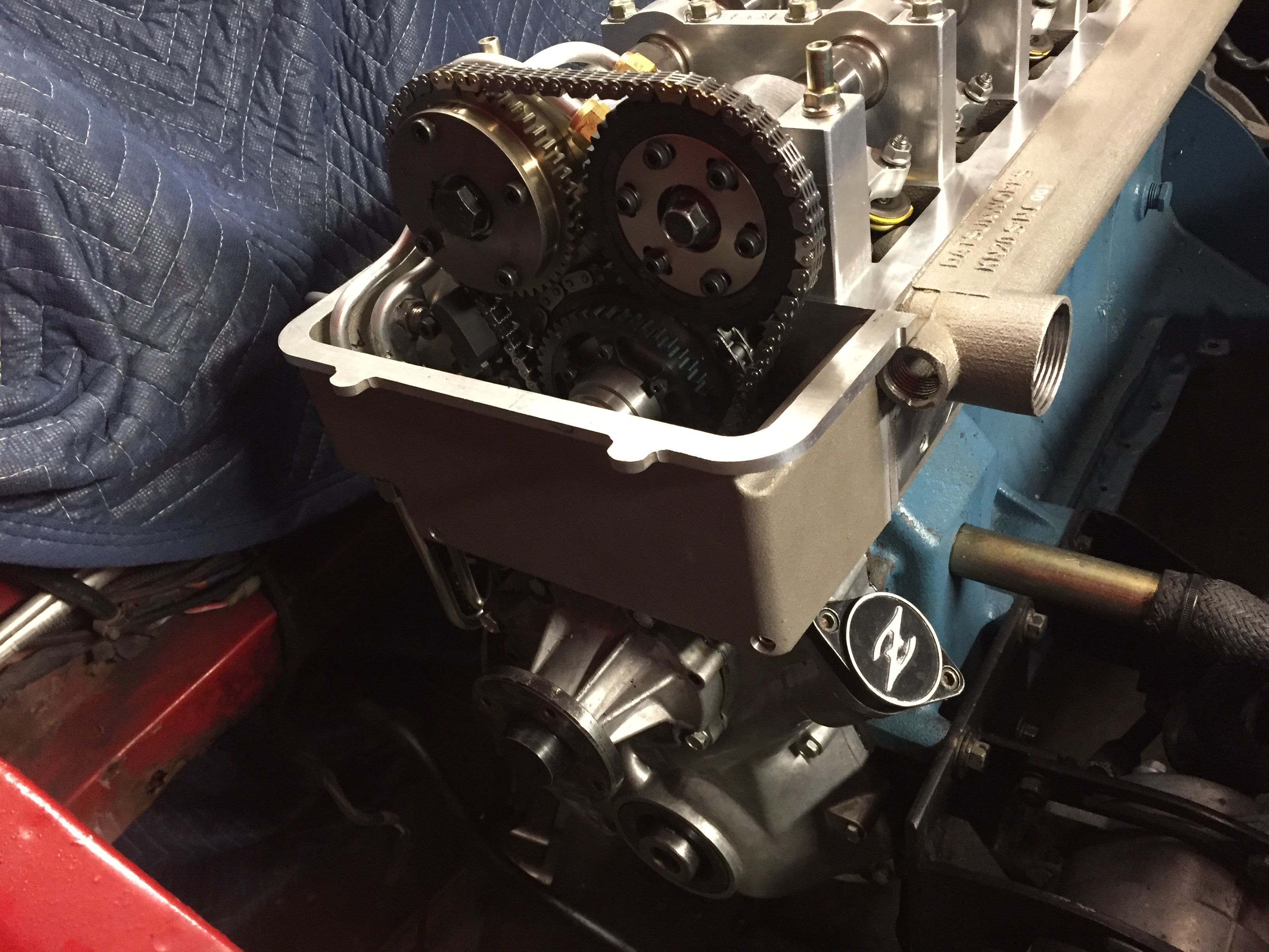
It feels really good finally making this work and short of any minor changes this is going to be the go to chain system for anyone running a single  row lower chain.
Catching up a bit.

So it’s been a while since I updated my blog and I wanted to bring it up to date.

When I left off I was just about to test the oiling system on my VVT prototype. Not sure why I stopped updating the blog at that point but most likely it was lack of free time.

So the good news is the VVT system works. I have over 7500 miles on my head and it’s doing great. The VVT is cool but the complexity of it plus the additional costs involved makes it at the far end of what I would recommend doing. There is a lot more bang for the buck you can get and the KN20 makes a ton of power on it’s own.

I have sold a total of ten heads. Unfortunately outside of mine only 3 of them have been completed and are on running motors. Not the fault of the heads but the realities of how long it can take to build performance engines. SN005 is on the road and has over 10K miles on it. SN010 is on a Z Car Garage build. It’s on the road but I’m not sure what kind of miles are on it.

So that is where things stand at the moment. Like a lot of things the pandemic has slowed/stopped momentum on sales but I’m seeing movement again. I’m in production on 5 more heads and 3 of those are already sold so I can’t really complain about that. I’m making some interesting changes to the head and the process so I will try and keep things current going forward. 

Thanks,

Derek

More progress

Almost at the point where I can test the oil system.


Front covers  on.

Internal lines finished.

And the externals are done as well.


Getting closer!

Hopefully Monday will be the pan and oil pump on and the first pressure test.

Cams are in!

So I’m actually on the way back up at this point. Got the head on and torqued down.


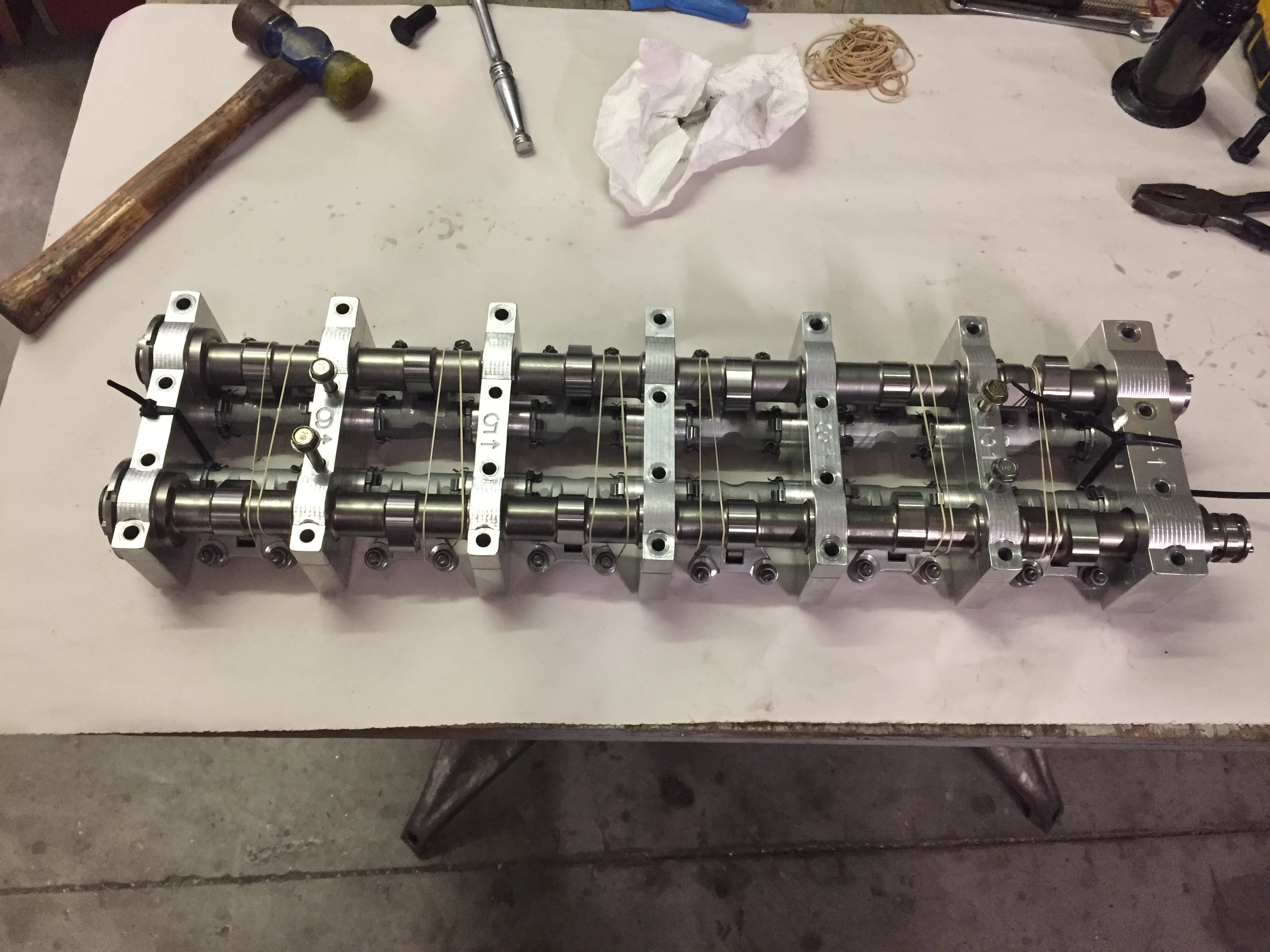
Bundled up to transport to the head.


This is one of the most tedious parts of the assembly. as you are tightening you are compressing springs and aligning dowels.

Next up chains and final cam timing

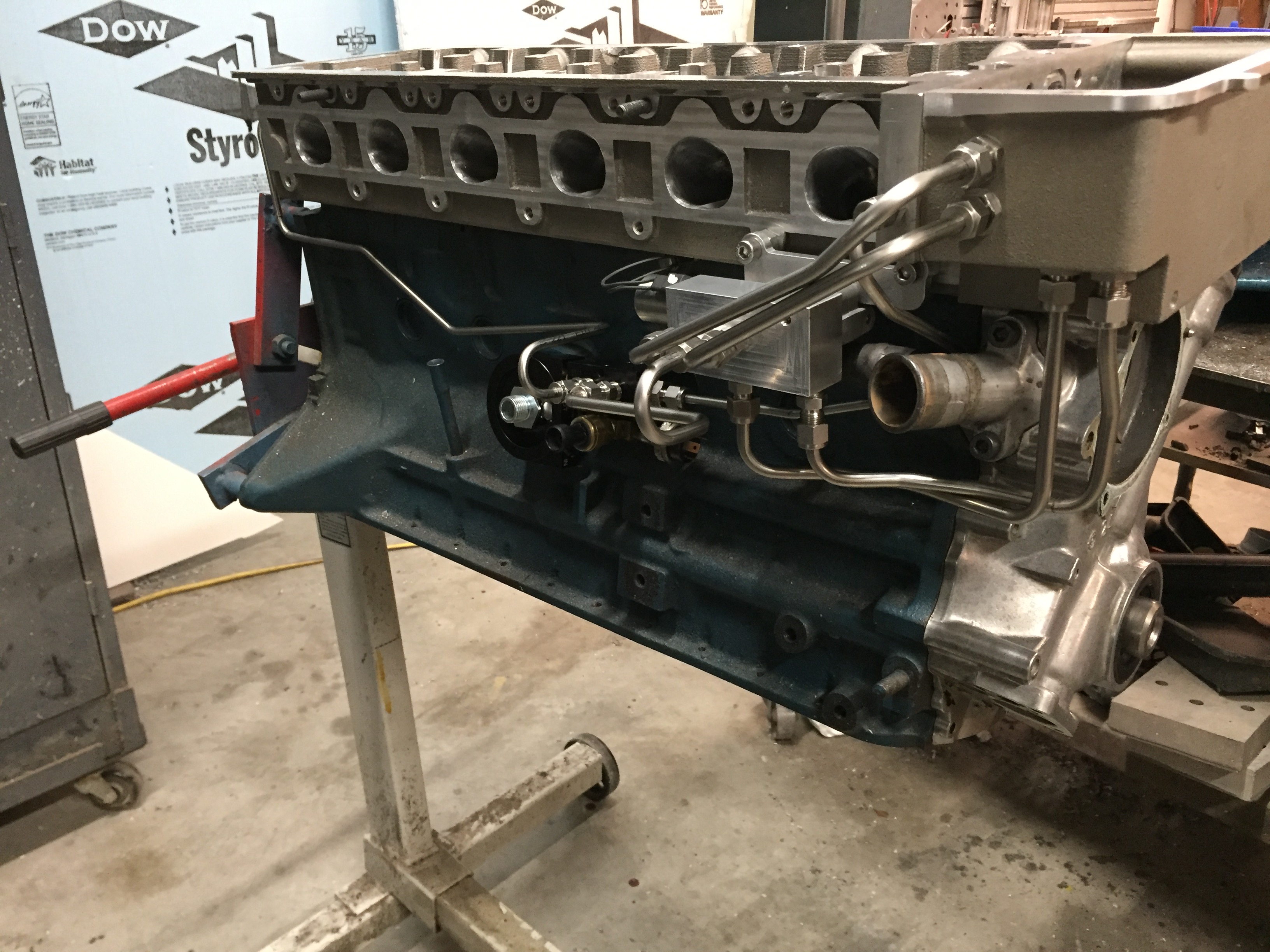
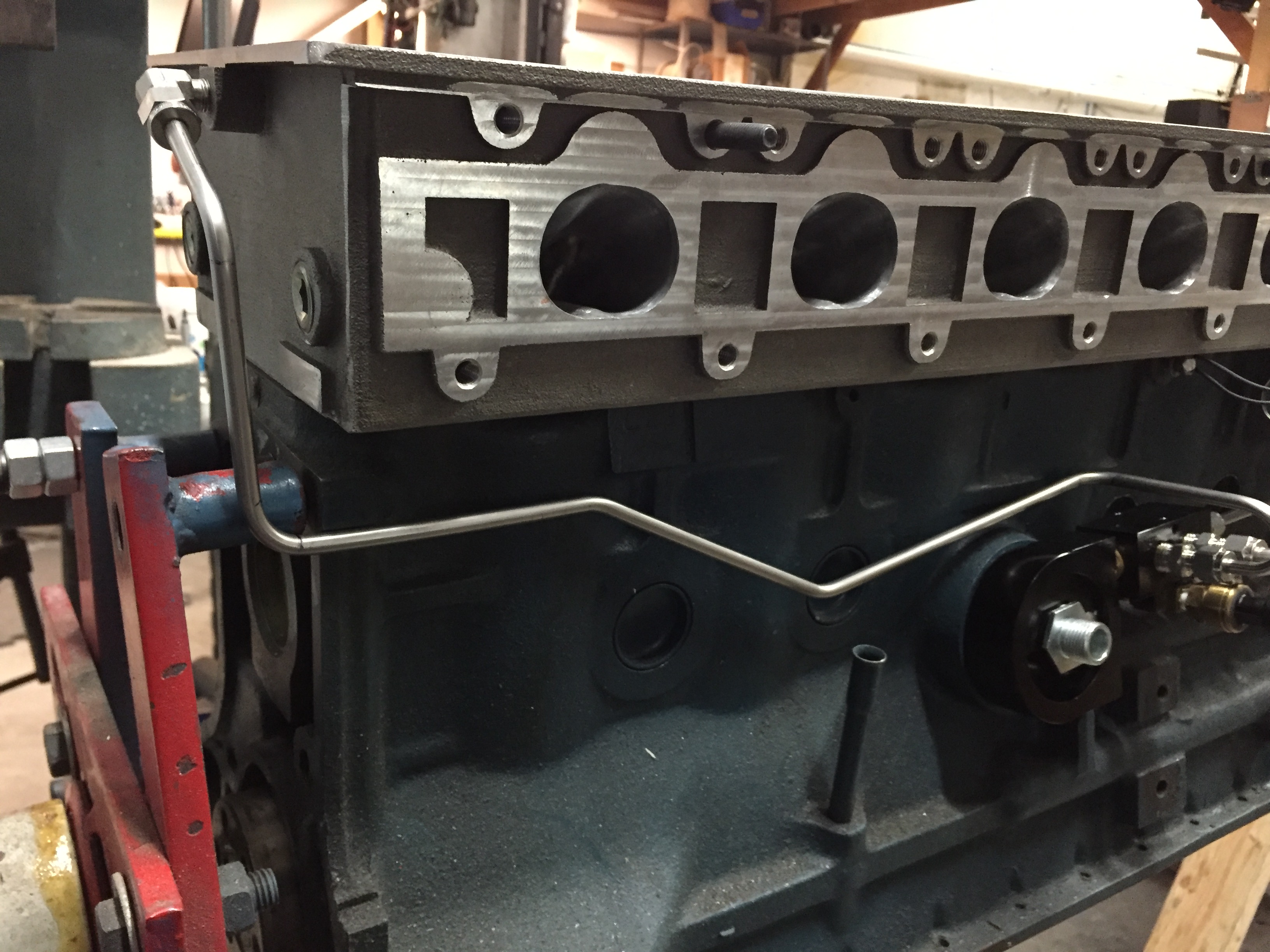
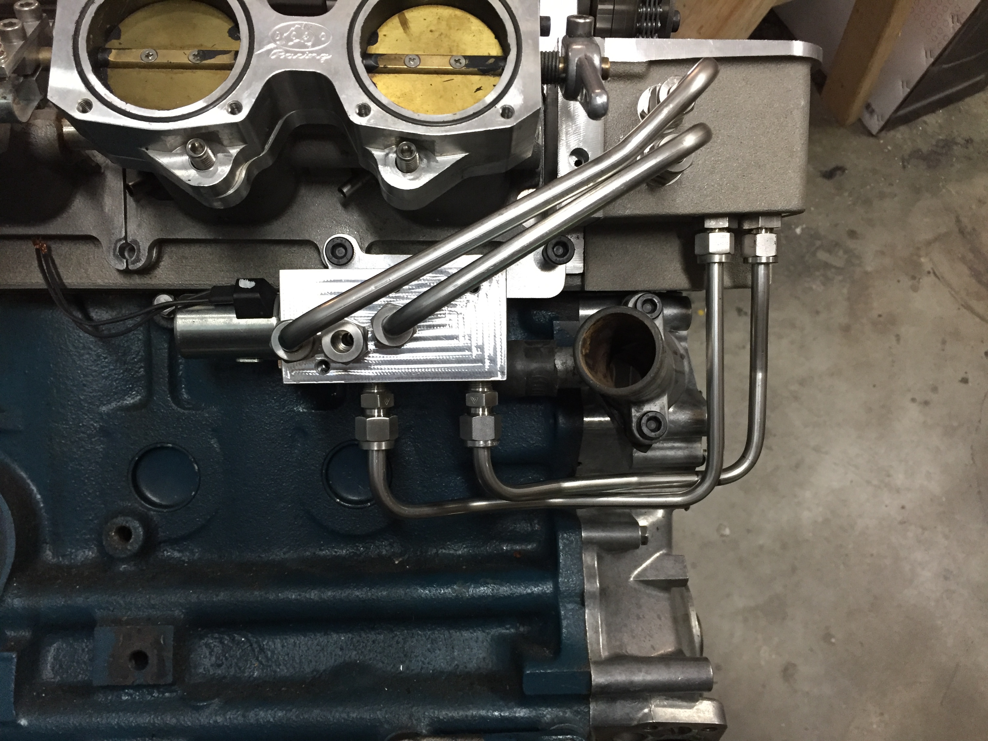
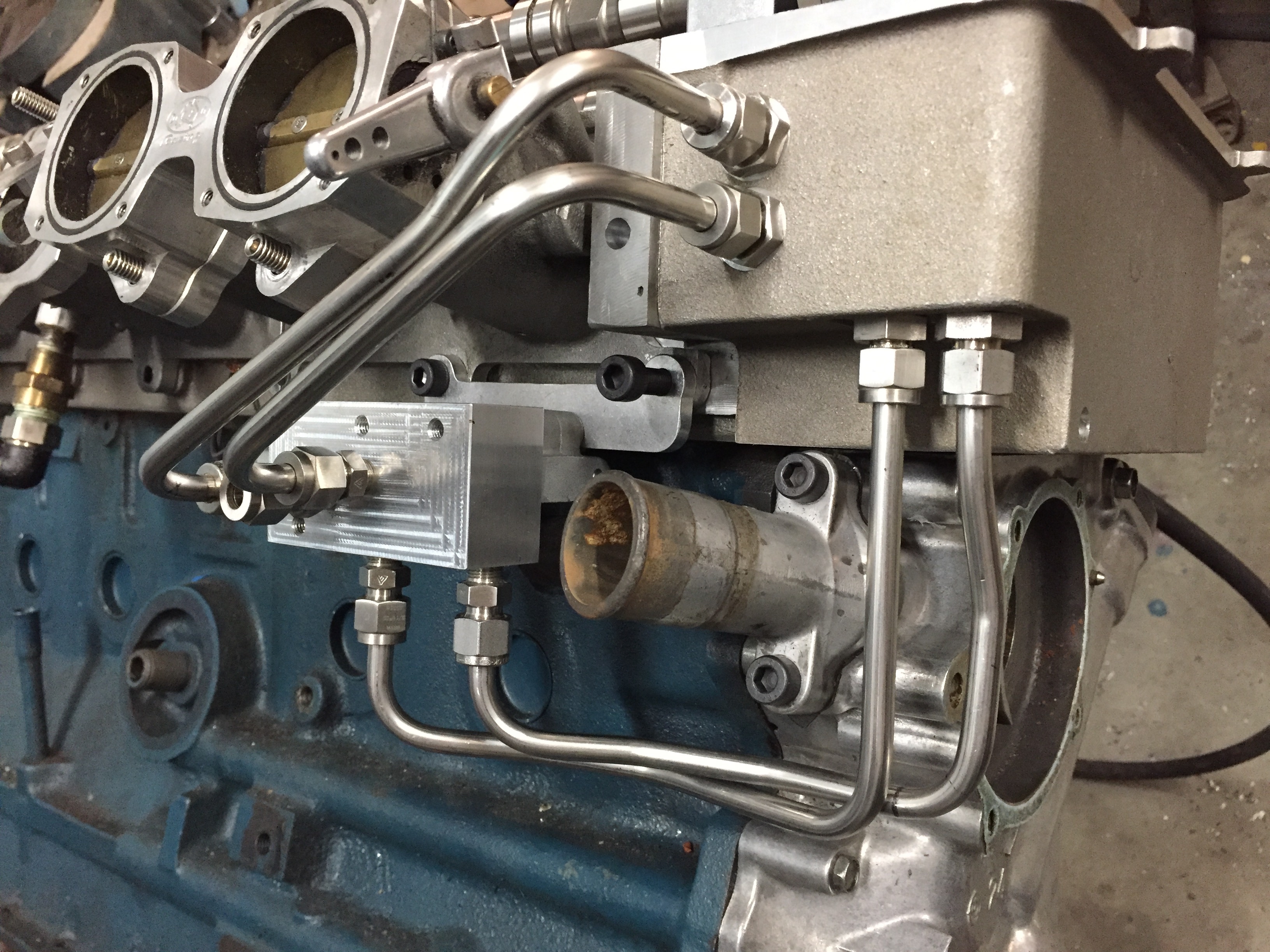
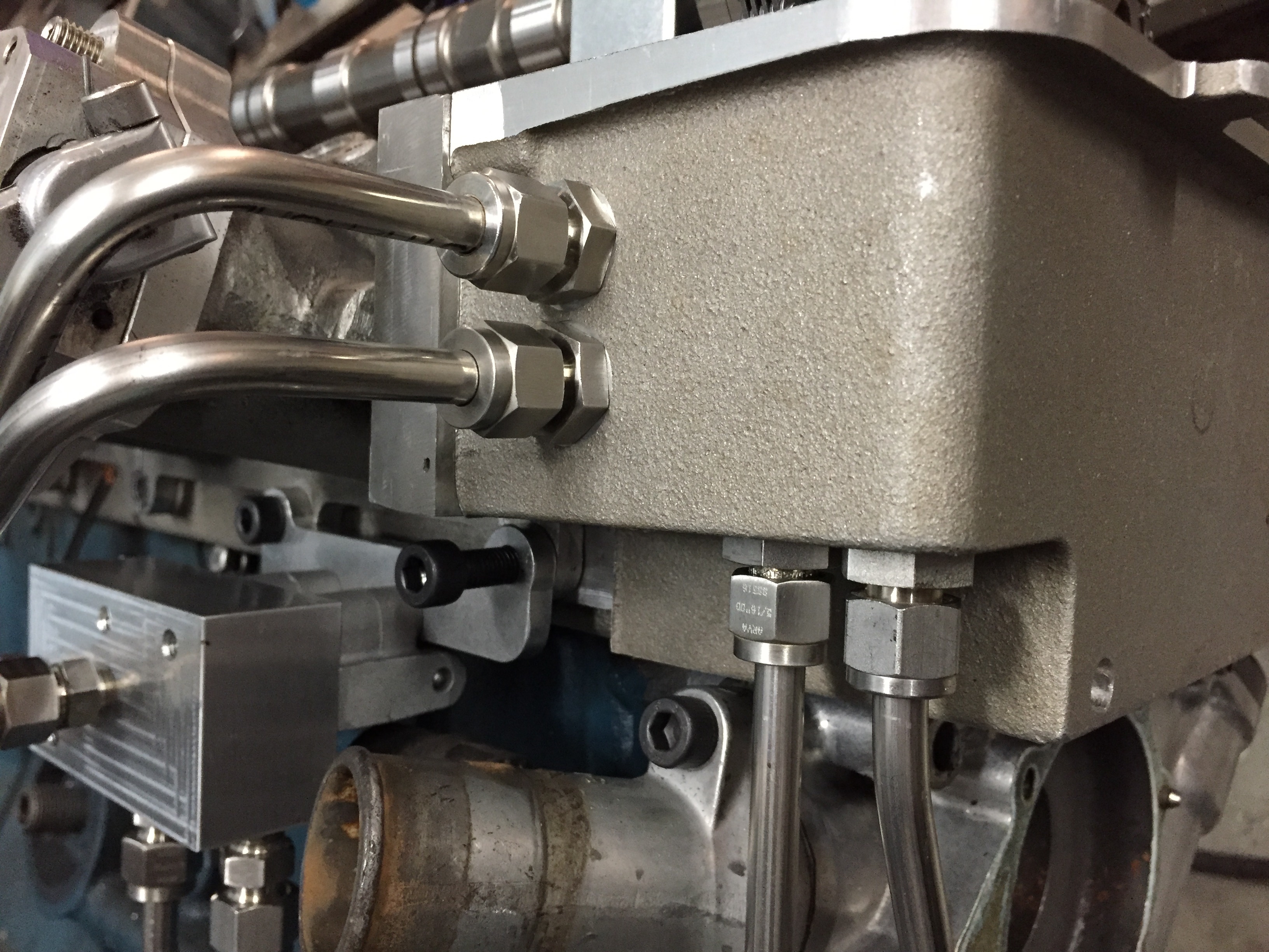
Exterior hard lines finished

Got everything fabed up. Very happy with the results.

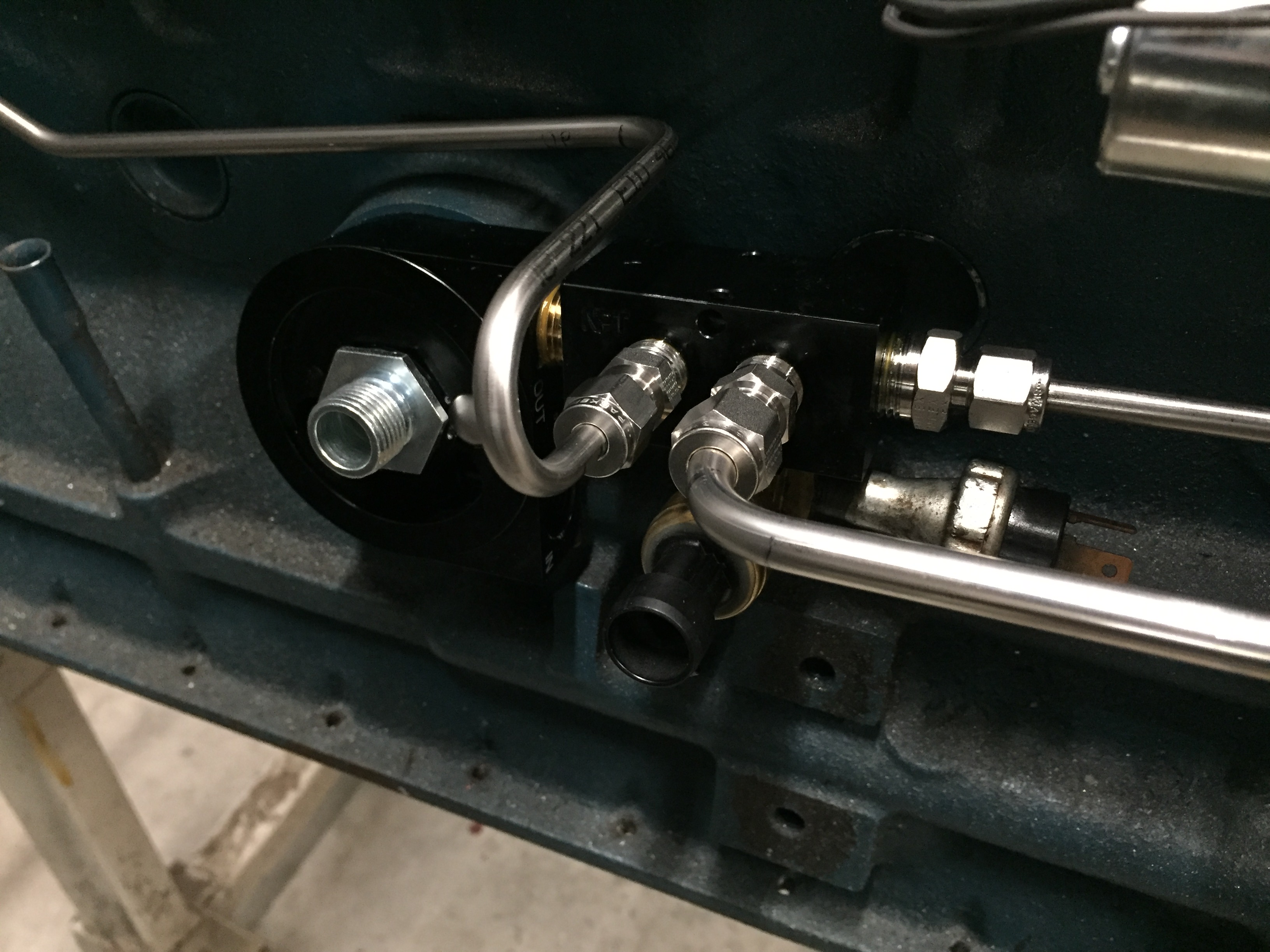
I added a sandwich adapter in order to be able to get more oil for the VCT. The oil pressure port was fine for the cam oil feeds but I felt it would not keep up with the VCT. I moved everything over to the sandwich plate. The oil pressure switches are still on the oil pressure port.

Rear oil feed.


Hard lines are a ton of effort but for me well worth it.

VCT Plumbing

Got the hardlines mostly done for the intake phaser control. Went well just tedious and time consuming.

The bottom two lines are advance and retard and the top two lines are returns. The center is the feed. They are 5/16 OD which gives me an ID that closely matches the Honda circuit.

It started off easy and then I remembered that an alternator needed to sit in there. That made things a little more interesting.

The bulkhead fittings worked out great.

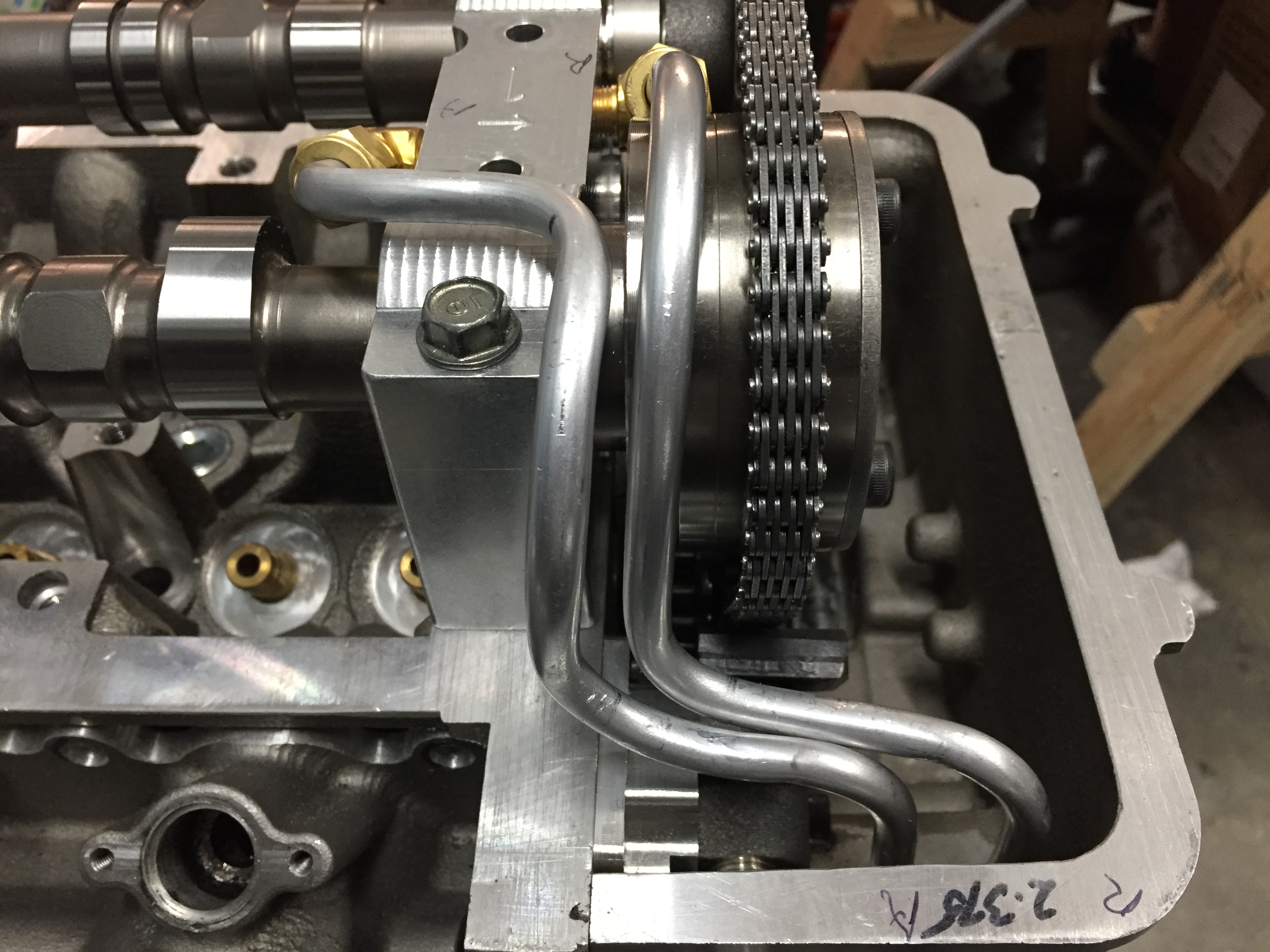
I chose to use soft aluminum tubing for the interior lines. I knew routing them was going to be a bitch and I wasn’t wrong. Looks a little rough but it will work. Non of the fittings are compressed yet. I’ll lock everything down during the final assembly and then tweak everything so they have clearance.

Feeding through the caps turned out to be a better way to go than through the tower bases.

I had to redesign the EDIS coil bracket since the valve was now in the way. It’s not as hidden as it used to be but when the throttle bodies and stacks are on it should be buried pretty well.

I’m super glad I went this route with the VCT valve. The look of it is exactly what I wanted and he hard lines fit the whole theme of the build.

Lots happening over the next few weeks as I try and finish it up and get it back in the car.

Bits and Pieces

Trying to get all all the incidental parts done so that when I get my head back from Xtreme I can concentrate on the final push. I’m locating the VCT valve in a different position than I had originally planed. I was unable to plumb it the way I wanted and that forced me to look at other options. I always hated the idea of hanging the valve off of the front of the timing cover. The control circuit is a little longer but I’m willing to take a chance for the sake of better looks.

Original 3D design:


Finished Product:


It will hang below intake #1 and will be mostly out of sight.


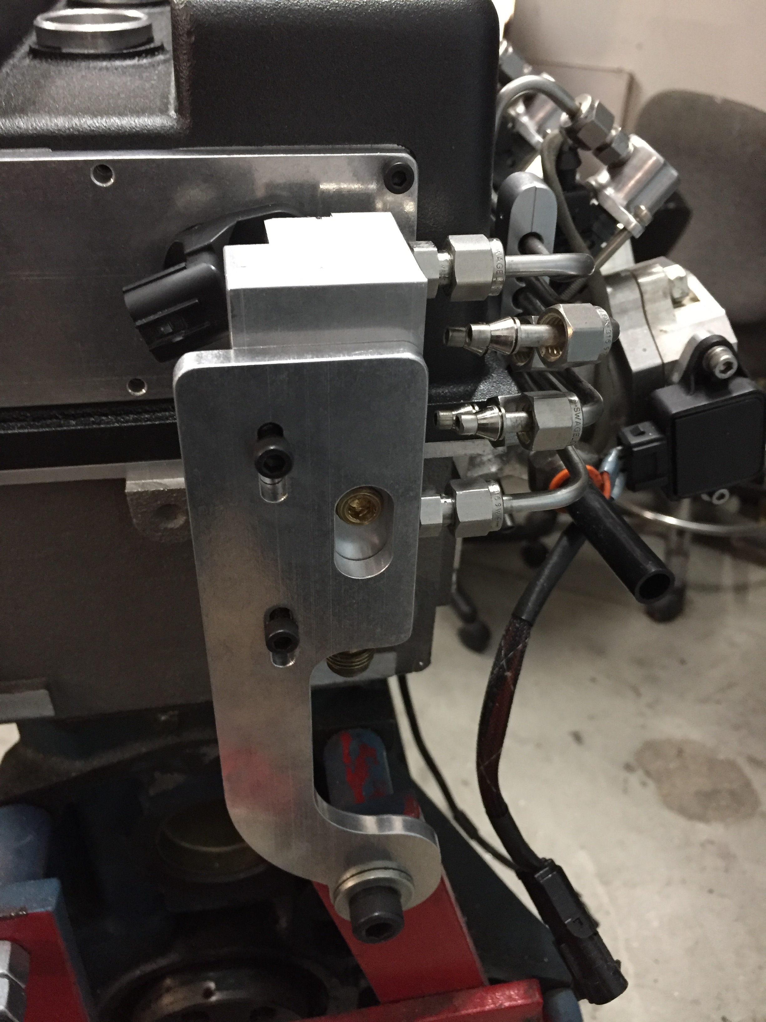
Made the CPS mount for the back of the valve cover. This required a pretty major rework of the fuel distribution block and a new mounting bracket. I got really lucky with the block in that I didn’t need to start from scratch.


Tight fit:)


It only took two versions of the CPS plate and fuel block brackets and one version of the VCT valve bracket. I must be getting the hang of this:)

Tall deck timing chain.

I’m convinced when they design a motor the first thing they do is the timing chain. Talk about restrictive.

SN005 is building a tall deck motor so I needed to work out what we were doing on the timing chain. I was hoping that my normal KA setup would work with a redesigned pivot for the tensioner arm.

Using my normal method of mocking up substituting plastic for metal. 

Actually worked out better than the normal setup. It looks like the extra height on the head will allow the arm to clear the timing cover without modifying the cover.

It uses all the stuff from a KA24 timing chain kit except the bottom chain needs to be a 94 link instead of the 92.

I was trying to get the arm closer to the tensioner but this is the best I’m going to get. Each full link you add or subtract shortens or lengthens the chain by 5/8” so the adjustment is pretty coarse.  The guides are stock out of the box Nissan KA24. The jumper brackets on the tension side are temporary. I’ll design something a little better.

I’m happy with the angle on the top tensioner. The upper brackets should start to become a standard item at this point. I changed the way the cam cores are being produced. I’m bringing the cams to length after heat treating and then shipping them to Schnieder for OD turning. This is giving me a lot more control.

This is what I settled on. A sub plate for the idler and a sub plate for the pivot guide and tensioner.

Then a spacer plate to bring the tensioner into the correct position.

I drilled the top gears so that they have 2.5 degrees adjustment and the cams are doweled to break that into 1.25 degree increments.


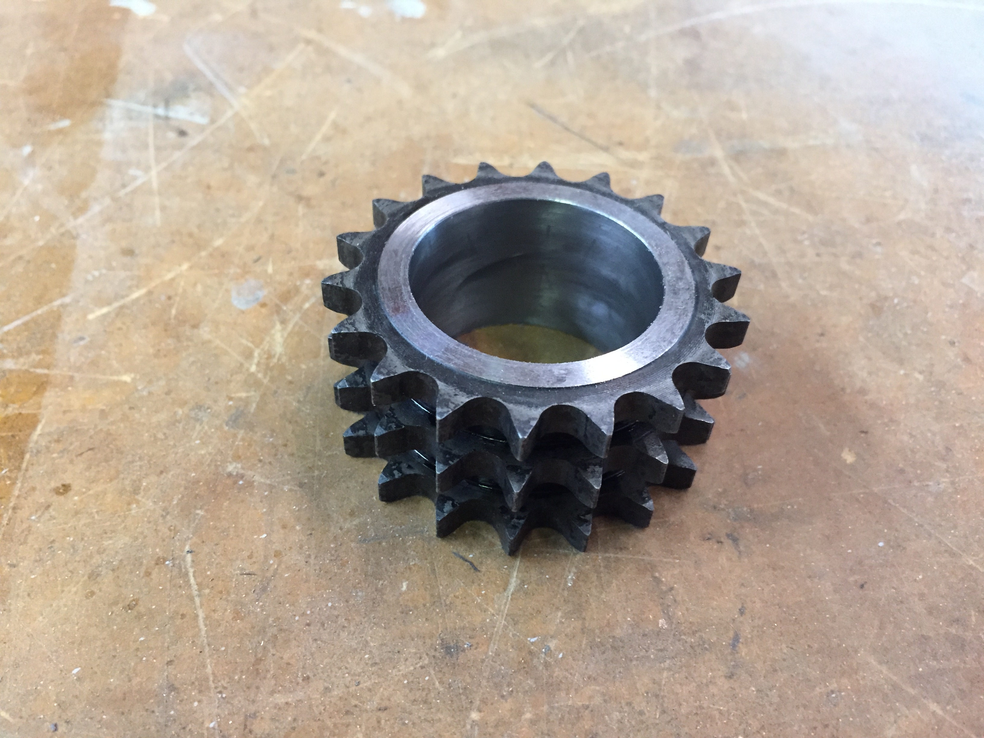
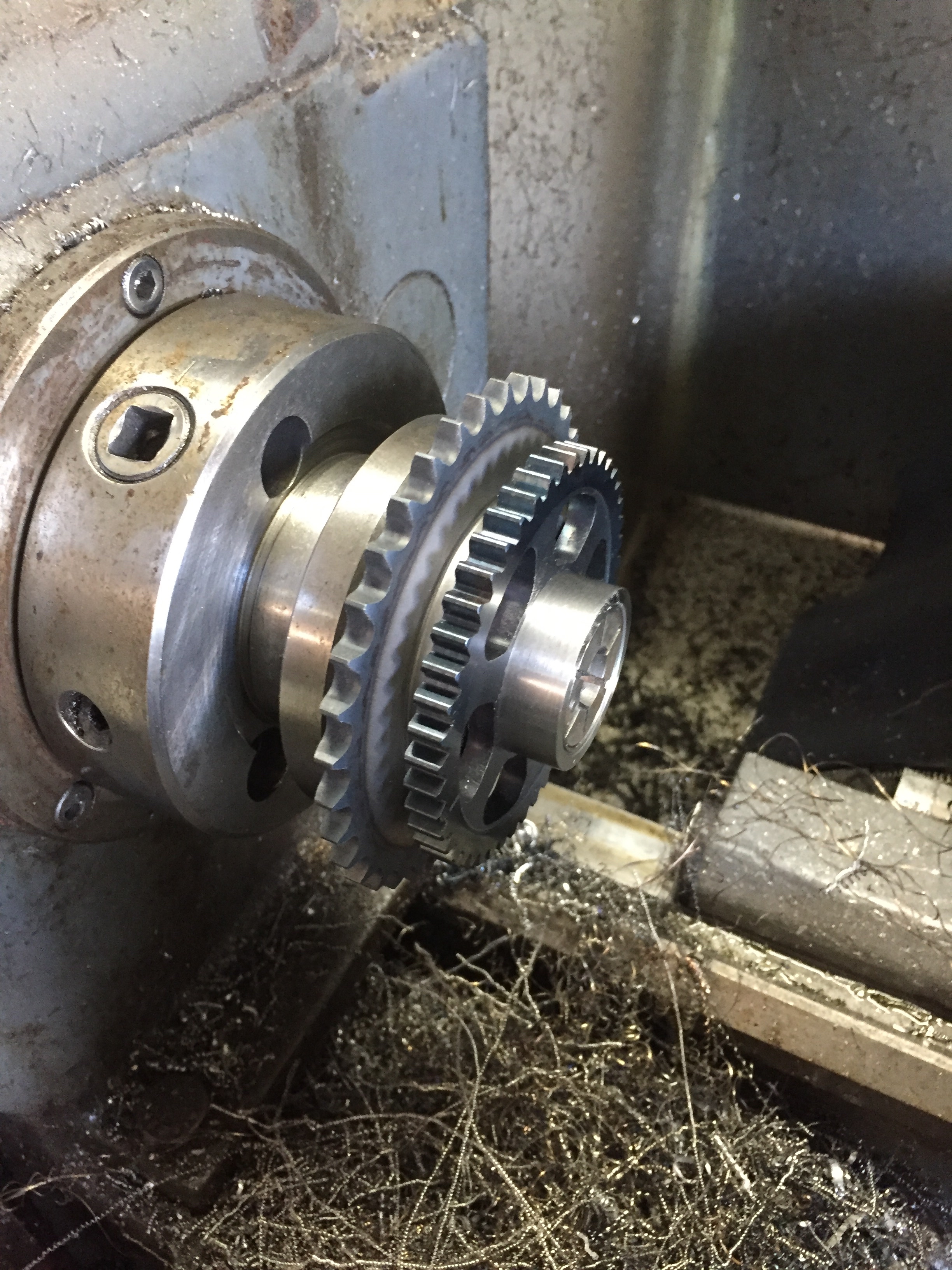
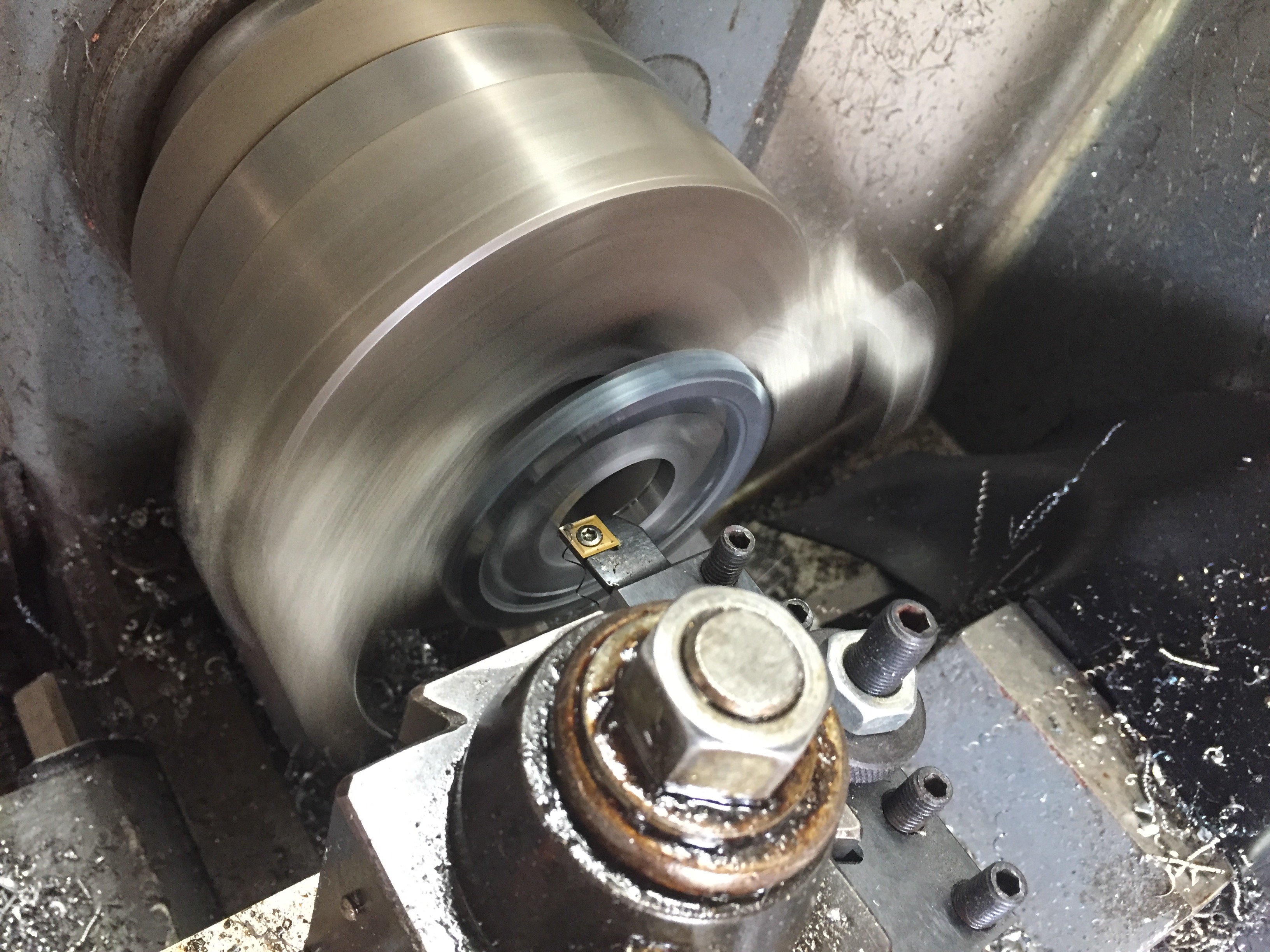
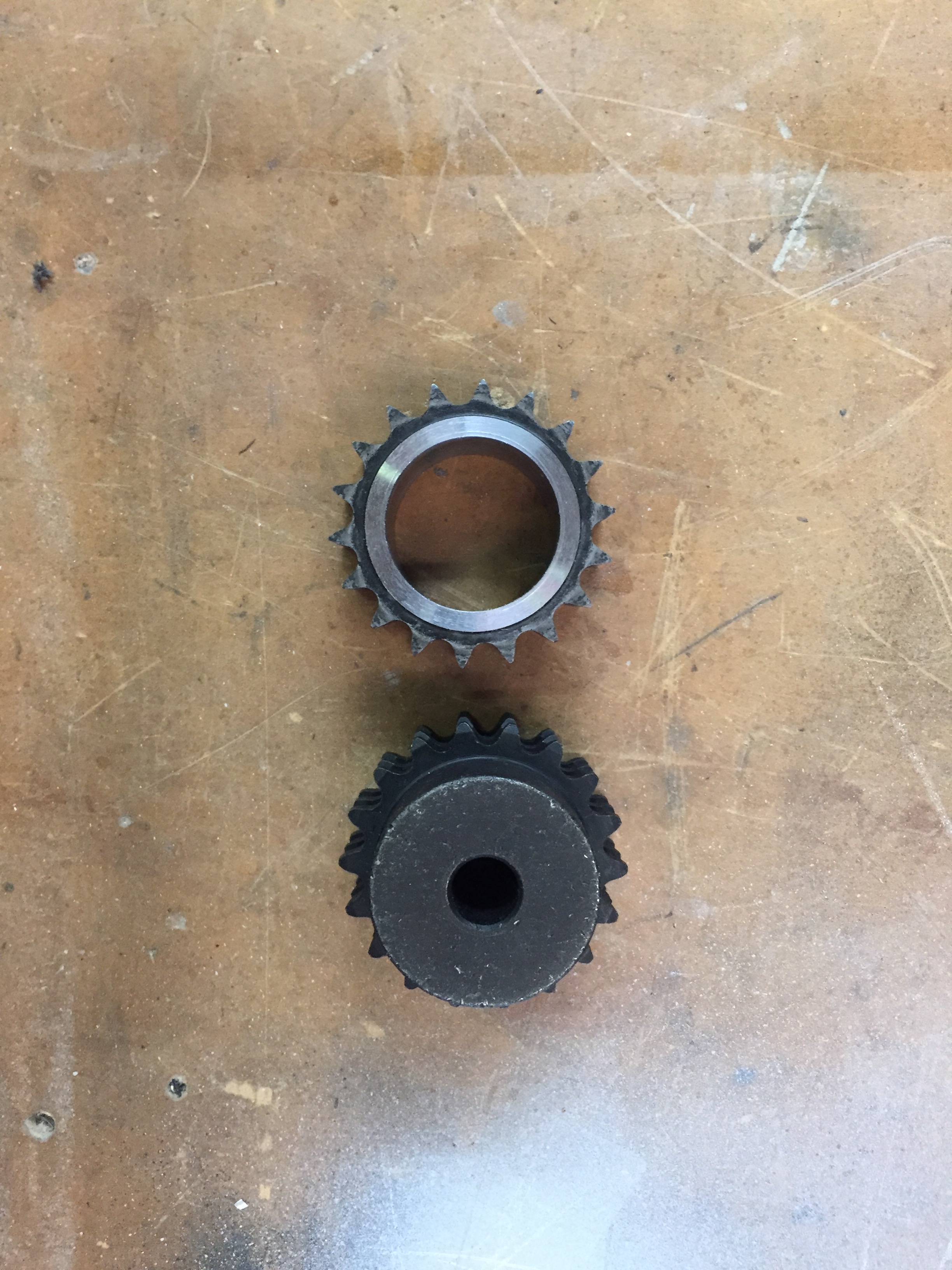
Bottom gear is new. It is a triplex 06P sprocket from Martin Sprocket with the teeth case hardened. I then bored, reamed and honed it out to 35mm.

Before and after.

The idea is that the inner and outer sprockets will provide strength to the middle driving set. This is way better than what I was running on the prototype. There is 3.5mm of adjustment front to rear via shim packs. This will make setting up the chains a lot easier.


Came together just fine.


Hopefully I’ll be able to get this kind of fit on the regular height blocks.

VCT Progress!

So slowly but surely I have been chipping away at making the VCT fit in the available space. What a freaking PIA. The problem with timing chains is you are constrained distance wise by the pitch of the chain and the adjustment can be a bit coarse.  Multiply that by two and you can see how it can get tricky. I model things the best I can in 3D but when it comes to something like this I find a hands on approach leads to a more satisfactory result.


Machined of the small gear from the KA24 idler.

I’m using a 5C expanding mandrel that I machined to fit.


Test fitting the Honda exhaust cam gear that I machined previously.

Happy with the fit for sure.


Quick test fit with the first idler sub plate. Looks good but I know from experience that there is a really long road from this point to the final fitting.

Here are the finalish mockup sub plates for the idler gear and the tensioner arm pivot. I may move the idler up another .010″ but I haven’t decided.

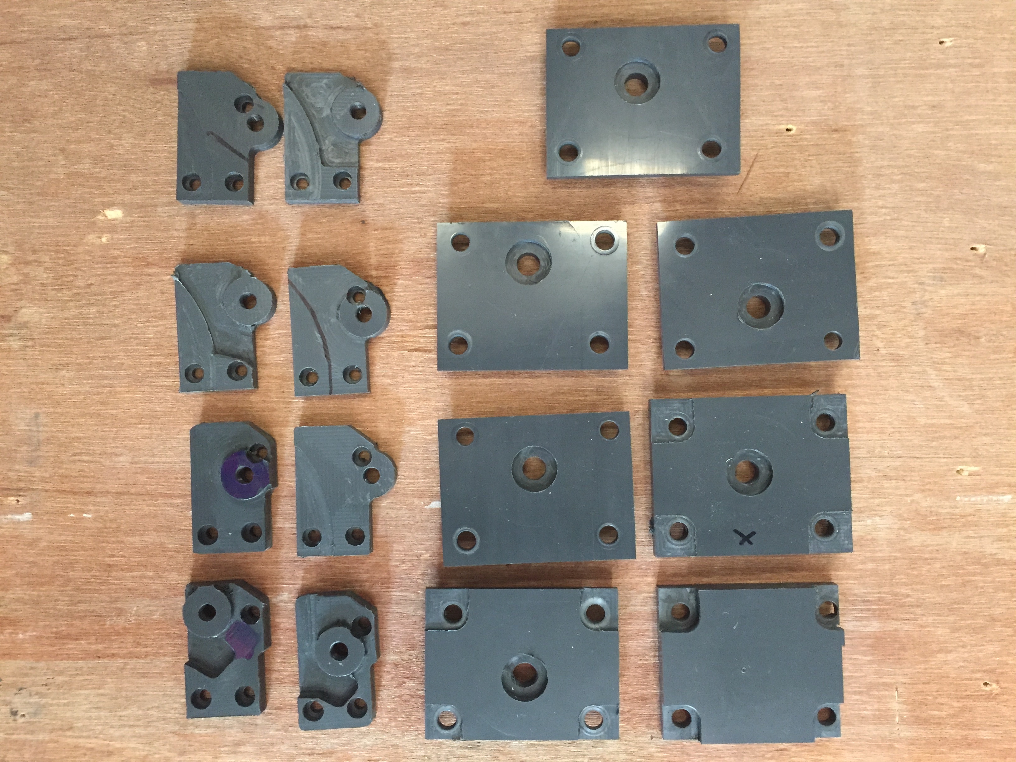
I do the majority of my prototyping in plastic. Easier to work with than aluminum and a lot cheaper. The idler plate will be steel and the pivot plate will be aluminum.


Upper tensioner mount.

The semi finished layout.

Upper tensioner is from a Mazda 626. Hybridz member Tioga turned me on to this one . I reshaped the contact shoe a bit and slapped it on there. It is a ratcheting style. They can be problematic if the lobe design on the cams are crappy. The constant pumping on the chain can break the pawls. I’m making the assumption at this point the Schneiders lobe design is a lot better than Cranes and won’t be a problem. I had to reshape the contact shoe and will probably work it some more if I stick with it.

Tight fit but the bottom line is….It fits. Which is a good thing since I committed to the cams before I knew for sure.  Unfortunately I can’t access the VCT oil ports on the head because the idler gear is covering them but I already designed a manifold as a work around.


So if the pictures make it look like this was a walk in the park here is a shot of the different versions of the sub plates I made to get the relationship between all those moving components the way I wanted them as well as fitting in the space I had to work with.


Starting on the VCT chain setup

Got the VTC cams back from Schneider so I was able to mess around a bit wit the upper chain.
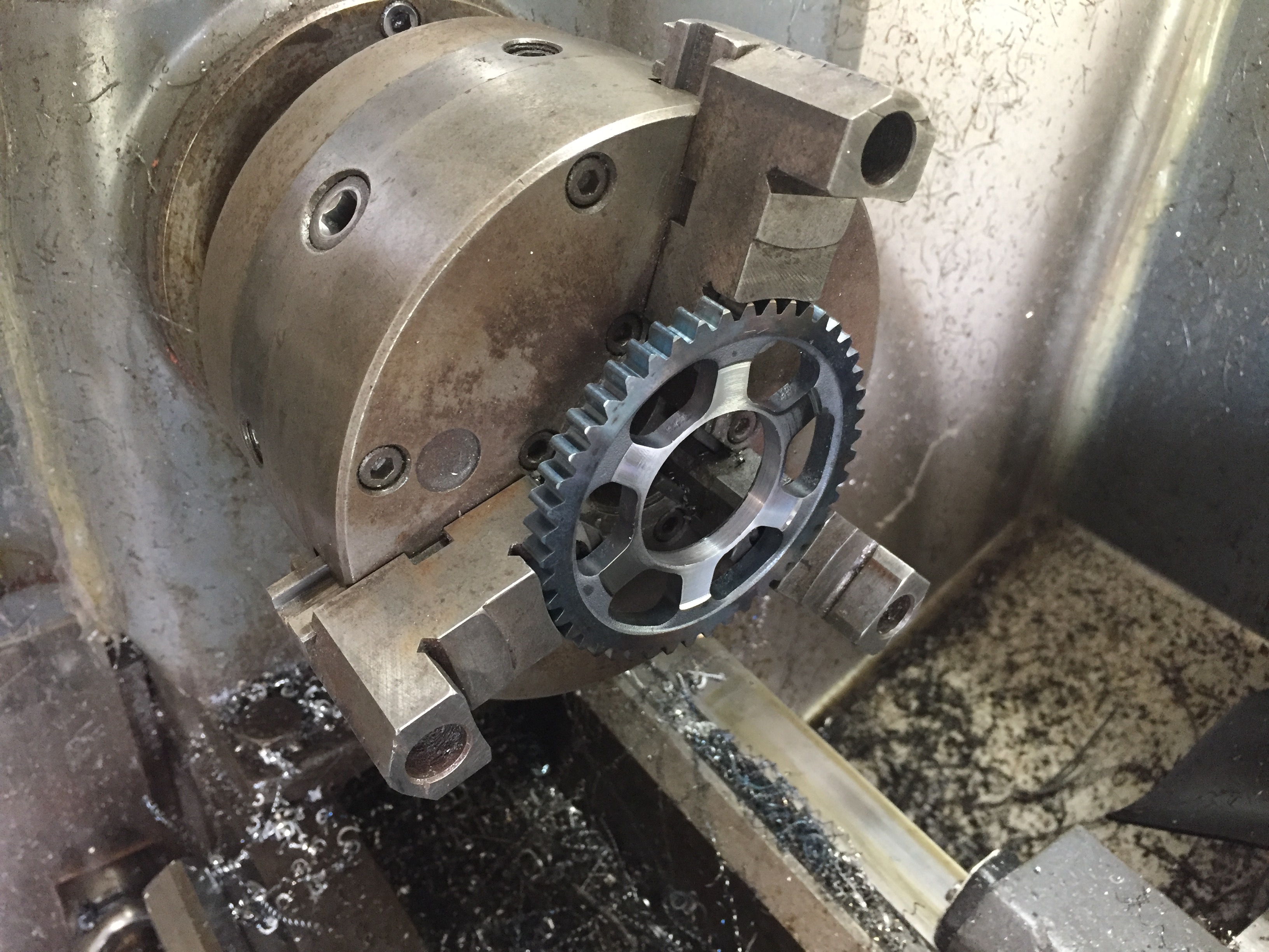
Machining the center out of a stock Honda exhaust gear. Holy bajezas was that thing hard. I had to anneal the center to make any headway through it. Came out great though.
Action shot


Looks promising but there is a lot left to do.


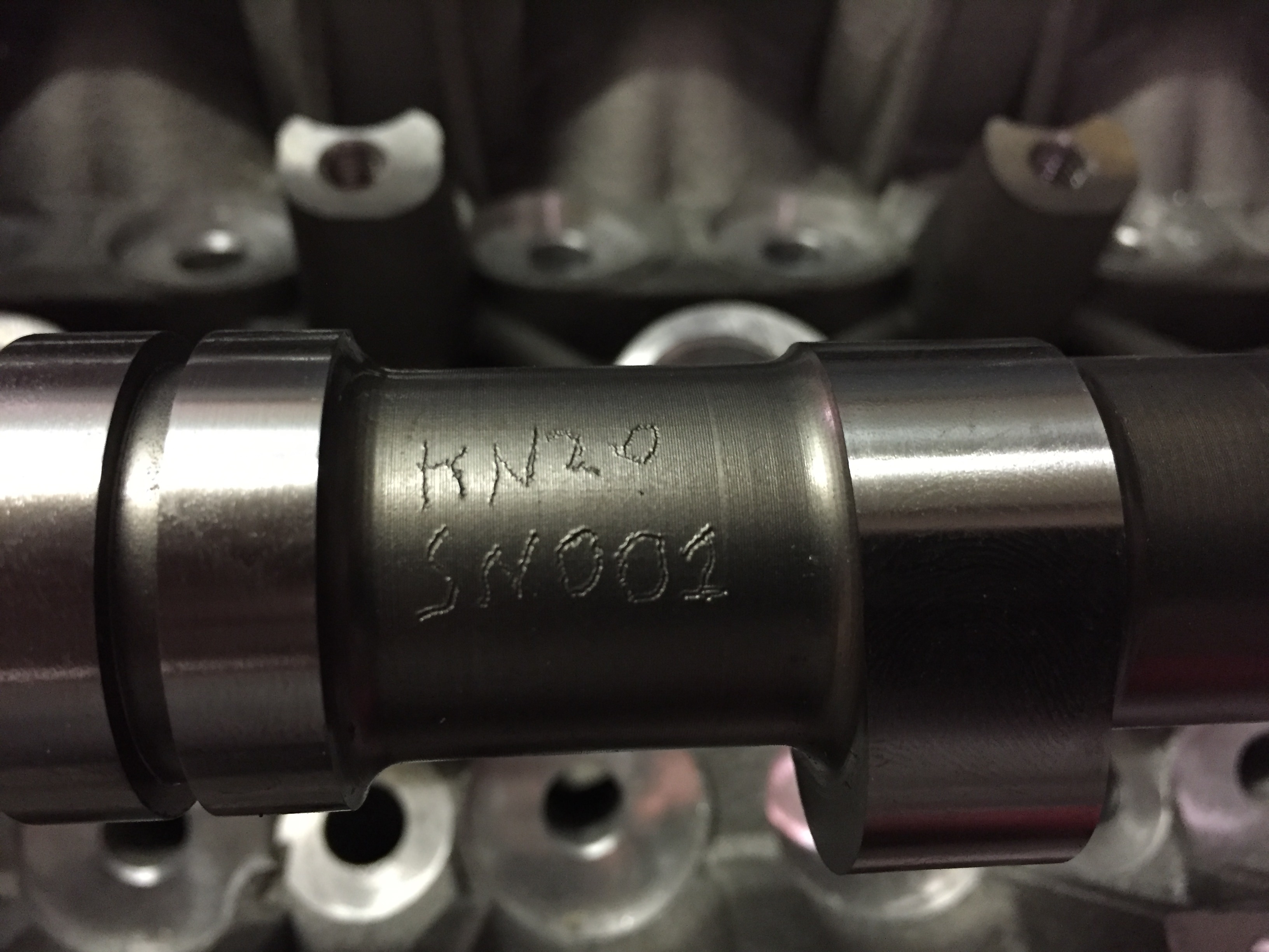
Best part is my stuff is always S/N001 :)